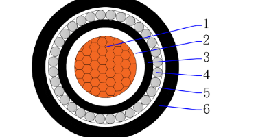
CU/XLPE/PVC/SWA/PVC 0.6/1kV Multicore armored cable
Multicore XLPE insulated PVC sheathed armored cable with copper conductor
Application:
To be used for main power supply such as in low voltage distribution power networks, indoor and outdoor areas. It can be installed in ducts, in dry or wet locations, recommended for direct burial where require higher electrical and mechanical protection.
Standard:
- Cable design: IEC 60502-1 or AS/ZNS 5000.1
- Conductor: IEC 60228 or AS/ZNS 1125
Construction
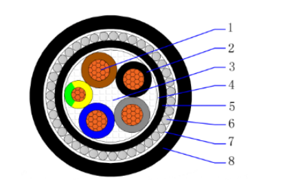
- 1. Conductor – Plain annealed class 2 stranded (compacted) copper
- 2. Insulation – Cross linked polyethylene (XLPE)
- 3. Filler – Non-hygroscopic material
- 4. Binder tape – Non-hygroscopic material tape
- 5. Inner sheath – Polyvinyl chloride compound (PVC)
- 6. Armor – Galvanized steel wires
- 7. Binder tape – Non-hygroscopic material tape
- 8. Outer sheath – Polyvinyl chloride compound (PVC)
Cross Section:
- 2C1.5~2C400mm2
- 3C1.5~3C400mm2
- 4C1.5~4C400mm2
- 5C1.5~5C400mm2
- 2C+E2.5~2C+E400mm2
- 3C+E2.5~3C+E400mm2
- 4C+E2.5~4C+E400mm2
Temperature characteristics:
- Conductor operating temperature: -15℃~90℃
- Min. temperatrue laying condition: 0℃
- Conductor emergency operating temperature: 105℃
- Conductor short-circuit operating temperature (5s): 250℃
Electrical Characteristics:
- Rated voltage: 0.6/1 (1.2) kV
- High voltage test: 3.5kV / 5min
Color:
- Insulation: According to customer requirements
- Outer sheath: Black or according to customer requirements
Minimum Bending Radius:
| Items | Single-core Cables | Three-core Cables | ||
| Unarmoured | Armoured | Unarmoured | Armoured | |
| Min. bending radius during installation | 20D | 15D | 15D | 12D |
| Min. bending radius close to connection box and termination (bending radius should be controlled carefully, if the molding guide plate is used) | 15D | 12D | 12D | 10D |
Applicable Standards
Optional
Technical Parameters
| No. of Cores and Nominal Cross Section | Min. Number of Wires | Nominal Insulation Thickness | Nominal Steel Wire Diameter | Nominal Sheath Thickness | Approx. Overall Diameter | Approx. Weight | Max. D.C. Resistance of Conductor at 20℃ |
| No. × mm² | No. | mm | mm | mm | mm | kg/km | ohm/km |
| 2×1.5 | 1 | 0.7 | 0.8 | 1.8 | 13.3 | 300 | 12.1 |
| 2×2.5 | 1 | 0.7 | 0.8 | 1.8 | 14.1 | 343 | 7.41 |
| 2×4 | 1 | 0.7 | 0.8 | 1.8 | 15.1 | 404 | 4.61 |
| 2×6 | 1 | 0.7 | 0.8 | 1.8 | 16.1 | 476 | 3.08 |
| 2×10 | 6 | 0.7 | 1.25 | 1.8 | 19.5 | 763 | 1.83 |
| 2×16 | 6 | 0.7 | 1.25 | 1.8 | 21.1 | 942 | 1.15 |
| 2×25 | 6 | 0.9 | 1.6 | 1.8 | 25 | 1384 | 0.727 |
| 2×35 | 6 | 0.9 | 1.6 | 1.8 | 27 | 1668 | 0.524 |
| 2×50 | 6 | 1 | 1.6 | 1.8 | 30 | 2061 | 0.387 |
| 2×70 | 12 | 1.1 | 1.6 | 2 | 33.8 | 2628 | 0.268 |
| 2×95 | 15 | 1.1 | 2 | 2.1 | 39.1 | 3649 | 0.193 |
| 2×120 | 18 | 1.2 | 2 | 2.2 | 42.5 | 4334 | 0.153 |
| 2×150 | 18 | 1.4 | 2 | 2.3 | 46.5 | 5134 | 0.124 |
| 2×185 | 30 | 1.6 | 2.5 | 2.5 | 52.3 | 6658 | 0.0991 |
| 2×240 | 34 | 1.7 | 2.5 | 2.7 | 57.7 | 8140 | 0.0754 |
| 2×300 | 34 | 1.8 | 2.5 | 2.8 | 63.1 | 9754 | 0.0601 |
| 2×400 | 53 | 2 | 2.5 | 3.1 | 70.1 | 12015 | 0.047 |
| No. of Cores and Nominal Cross Section | Min. Number of Wires | Nominal Insulation Thickness | Nominal Steel Wire Diameter | Nominal Sheath Thickness | Approx. Overall Diameter | Approx. Weight | Max. D.C. Resistance of Conductor at 20℃ |
| No. × mm² | No. | mm | mm | mm | mm | kg/km | ohm/km |
| 3×1.5 | 1 | 0.7 | 0.8 | 1.8 | 13.8 | 331 | 12.1 |
| 3×2.5 | 1 | 0.7 | 0.8 | 1.8 | 14.6 | 384 | 7.41 |
| 3×4 | 1 | 0.7 | 0.8 | 1.8 | 15.6 | 460 | 4.61 |
| 3×6 | 1 | 0.7 | 0.8 | 1.8 | 16.7 | 552 | 3.08 |
| 3×10 | 6 | 0.7 | 1.25 | 1.8 | 20.4 | 889 | 1.83 |
| 3×16 | 6 | 0.7 | 1.25 | 1.8 | 22.1 | 1133 | 1.15 |
| 3×25 | 6 | 0.9 | 1.6 | 1.8 | 26.2 | 1680 | 0.727 |
| 3X35 | 6 | 0.9 | 1.6 | 1.8 | 28.4 | 2051 | 0.524 |
| 3×50 | 6 | 1 | 1.6 | 1.9 | 31.8 | 2572 | 0.387 |
| 3×70 | 12 | 1.1 | 2 | 2 | 37.2 | 3637 | 0.268 |
| 3×95 | 15 | 1.1 | 2 | 2.2 | 41.5 | 4626 | 0.193 |
| 3×120 | 18 | 1.2 | 2 | 2.3 | 45.2 | 5565 | 0.153 |
| 3×150 | 18 | 1.4 | 2.5 | 2.5 | 51.1 | 7121 | 0.124 |
| 3×185 | 30 | 1.6 | 2.5 | 2.6 | 55.6 | 8522 | 0.0991 |
| 3×240 | 34 | 1.7 | 2.5 | 2.8 | 61.8 | 10612 | 0.0754 |
| 3×300 | 34 | 1.8 | 2.5 | 3 | 67.4 | 12798 | 0.0601 |
| 3×400 | 53 | 2 | 2.5 | 3.2 | 74.7 | 15826 | 0.047 |
| No. of Cores and Nominal Cross Section | Min. Number of Wires | Nominal Insulation Thickness | Nominal Steel Wire Diameter | Nominal Sheath Thickness | Approx. Overall Diameter | Approx. Weight | Max. D.C. Resistance of Conductor at 20℃ |
| No. × mm² | No. | mm | mm | mm | mm | kg/km | ohm/km |
| 4×1.5 | 1 | 0.7 | 0.8 | 1.8 | 14.5 | 372 | 12.1 |
| 4×2.5 | 1 | 0.7 | 0.8 | 1.8 | 15.4 | 435 | 7.41 |
| 4×4 | 1 | 0.7 | 0.8 | 1.8 | 16.6 | 531 | 4.61 |
| 4×6 | 1 | 0.7 | 1.25 | 1.8 | 18.7 | 765 | 3.08 |
| 4×10 | 6 | 0.7 | 1.25 | 1.8 | 21.8 | 1049 | 1.83 |
| 4×16 | 6 | 0.7 | 1.6 | 1.8 | 24.4 | 1473 | 1.15 |
| 4×25 | 6 | 0.9 | 1.6 | 1.8 | 28.3 | 2017 | 0.727 |
| 4×35 | 6 | 0.9 | 1.6 | 1.9 | 30.9 | 2495 | 0.524 |
| 4×50 | 6 | 1 | 1.6 | 2 | 34.7 | 3157 | 0.387 |
| 4×70 | 12 | 1.1 | 2 | 2.2 | 40.7 | 4493 | 0.268 |
| 4×95 | 15 | 1.1 | 2 | 2.3 | 45.3 | 5742 | 0.193 |
| 4×120 | 18 | 1.2 | 2.5 | 2.5 | 51 | 7417 | 0.153 |
| 4×150 | 18 | 1.4 | 2.5 | 2.6 | 55.8 | 8806 | 0.124 |
| 4×185 | 30 | 1.6 | 2.5 | 2.8 | 61.4 | 10739 | 0.0991 |
| 4×240 | 34 | 1.7 | 2.5 | 3 | 67.9 | 13321 | 0.0754 |
| 4×300 | 34 | 1.8 | 2.5 | 3.2 | 74.1 | 16097 | 0.0601 |
| 4×400 | 53 | 2 | 3.15 | 3.5 | 84.1 | 21074 | 0.047 |
| No. of Cores and Nominal Cross Section | Min. Number of Wires | Nominal Insulation Thickness | Nominal Steel Wire Diameter | Nominal Sheath Thickness | Approx. Overall Diameter | Approx. Weight | Max. D.C. Resistance of Conductor at 20℃ |
| No. × mm² | No. | mm | mm | mm | mm | kg/km | ohm/km |
| 5×1.5 | 1 | 0.7 | 0.8 | 1.8 | 15.3 | 414 | 12.1 |
| 5×2.5 | 1 | 0.7 | 0.8 | 1.8 | 16.3 | 492 | 7.41 |
| 5×4 | 1 | 0.7 | 1.25 | 1.8 | 18.5 | 726 | 4.61 |
| 5×6 | 1 | 0.7 | 1.25 | 1.8 | 19.9 | 874 | 3.08 |
| 5×10 | 6 | 0.7 | 1.25 | 1.8 | 23.3 | 1214 | 1.83 |
| 5×16 | 6 | 0.7 | 1.6 | 1.8 | 26.1 | 1723 | 1.15 |
| 5×25 | 6 | 0.9 | 1.6 | 1.8 | 30.5 | 2362 | 0.727 |
| 5×35 | 6 | 0.9 | 1.6 | 1.9 | 33.4 | 2953 | 0.524 |
| 5×50 | 6 | 1 | 2 | 2.1 | 39.3 | 4090 | 0.387 |
| 5×70 | 12 | 1.1 | 2 | 2.3 | 44.3 | 5352 | 0.268 |
| 5×95 | 15 | 1.1 | 2.5 | 2.5 | 51 | 7379 | 0.193 |
| 5×120 | 18 | 1.2 | 2.5 | 2.6 | 55.5 | 8856 | 0.153 |
| 5×150 | 18 | 1.4 | 2.5 | 2.8 | 61.4 | 10690 | 0.124 |
| 5×185 | 30 | 1.6 | 2.5 | 3 | 67.2 | 12917 | 0.0991 |
| 5×240 | 34 | 1.7 | 2.5 | 3.2 | 74.4 | 16133 | 0.0754 |
| 5×300 | 34 | 1.8 | 3.15 | 3.4 | 82.9 | 20582 | 0.0601 |
| 5×400 | 53 | 2 | 3.15 | 3.8 | 92.4 | 25587 | 0.047 |
| No. of Cores and Nominal Cross Section | Min. Number of Wires | Nominal Insulation Thickness | Nominal Steel Wire Diameter | Nominal Sheath Thickness | Approx. Overall Diameter | Approx. Weight | Max. D.C. Resistance of Conductor at 20℃ |
| No. × mm² | No. | mm | mm | mm | mm | kg/km | ohm/km |
| 3×2.5+1×1.5 | 1/1 | 0.7/0.7 | 0.8 | 1.8 | 15.2 | 418 | 7.41/12.1 |
| 3×4+1×2.5 | 1/1 | 0.7/0.7 | 0.8 | 1.8 | 16.3 | 508 | 4.61/7.41 |
| 3×6+1×4 | 1/1 | 0.7/0.7 | 1.25 | 1.8 | 18.4 | 740 | 3.08/4.61 |
| 3×10+1×6 | 6/1 | 0.7/0.7 | 1.25 | 1.8 | 21 | 977 | 1.83/3.08 |
| 3×16+1×10 | 6/6 | 0.7/0.7 | 1.25 | 1.8 | 23.2 | 1268 | 1.15/1.83 |
| 3×25+1×16 | 6/6 | 0.9/0.7 | 1.6 | 1.8 | 27.3 | 1879 | 0.727/1.15 |
| 3×35+1×16 | 6/6 | 0.9/0.7 | 1.6 | 1.8 | 29.1 | 2225 | 0.524/1.15 |
| 3×50+1×25 | 6/6 | 1.0/0.9 | 1.6 | 1.9 | 33 | 2856 | 0.387/0.727 |
| 3×70+1×35 | 12/6 | 1.1/0.9 | 2 | 2.1 | 38.6 | 4045 | 0.268/0.524 |
| 3×95+1×50 | 15/6 | 1.1/1.0 | 2 | 2.2 | 43 | 5162 | 0.193/0.387 |
| 3×120+1×70 | 18/12 | 1.2/1.1 | 2 | 2.4 | 47.3 | 6325 | 0.153/0.268 |
| 3×150+1×70 | 18/12 | 1.4/1.1 | 2.5 | 2.5 | 52.4 | 7841 | 0.124/0.268 |
| 3×185+1×95 | 30/15 | 1.6/1.1 | 2.5 | 2.7 | 57.5 | 9512 | 0.0991/0.193 |
| 3×240+1×120 | 34/18 | 1.7/1.2 | 2.5 | 2.9 | 63.8 | 11870 | 0.0754/0.153 |
| 3×300+1×150 | 34/18 | 1.8/1.4 | 2.5 | 3 | 69.5 | 14254 | 0.0601/0.124 |
| 3×400+1×185 | 53/30 | 2.0/1.6 | 3.15 | 3.3 | 78.8 | 18672 | 0.0470/0.0991 |
| No. of Cores and Nominal Cross Section | Min. Number of Wires | Nominal Insulation Thickness | Nominal Steel Wire Diameter | Nominal Sheath Thickness | Approx. Overall Diameter | Approx. Weight | Max. D.C. Resistance of Conductor at 20℃ |
| No. × mm² | No. | mm | mm | mm | mm | kg/km | ohm/km |
| 3×2.5+2×1.5 | 1/1 | 0.7/0.7 | 0.8 | 1.8 | 15.9 | 459 | 7.41/12.1 |
| 3×4+2×2.5 | 1/1 | 0.7/0.7 | 1.25 | 1.8 | 18 | 678 | 4.61/7.41 |
| 3×6+2×4 | 1/1 | 0.7/0.7 | 1.25 | 1.8 | 19.3 | 817 | 3.08/4.61 |
| 3×10+2×6 | 6/1 | 0.7/0.7 | 1.25 | 1.8 | 21.9 | 1073 | 1.83/3.08 |
| 3×16+2×10 | 6/6 | 0.7/0.7 | 1.6 | 1.8 | 25.3 | 1565 | 1.15/1.83 |
| 3×25+2×16 | 6/6 | 0.9/0.7 | 1.6 | 1.8 | 28.7 | 2106 | 0.727/1.15 |
| 3×35+2×16 | 6/6 | 0.9/0.7 | 1.6 | 1.8 | 30.4 | 2448 | 0.524/1.15 |
| 3×50+2×25 | 6/6 | 1.0/0.9 | 2 | 2 | 36.4 | 3499 | 0.387/0.727 |
| 3×70+2×35 | 12/6 | 1.1/0.9 | 2 | 2.1 | 40.4 | 4487 | 0.268/0.524 |
| 3×95+2×50 | 15/6 | 1.1/1.0 | 2 | 2.3 | 45.4 | 5750 | 0.193/0.387 |
| 3×120+2×70 | 18/12 | 1.2/1.1 | 2.5 | 2.5 | 51.6 | 7638 | 0.153/0.268 |
| 3×150+2×70 | 18/12 | 1.4/1.1 | 2.5 | 2.6 | 54.9 | 8637 | 0.124/0.268 |
| 3×185+2×95 | 30/15 | 1.6/1.1 | 2.5 | 2.8 | 60.9 | 10700 | 0.0991/0.193 |
| 3×240+2×120 | 34/18 | 1.7/1.2 | 2.5 | 3 | 67 | 13208 | 0.0754/0.153 |
| 3×300+2×150 | 34/18 | 1.8/1.4 | 2.5 | 3.2 | 73.4 | 15945 | 0.0601/0.124 |
| 3×400+2×185 | 53/30 | 2.0/1.6 | 3.15 | 3.5 | 83 | 20775 | 0.0470/0.0991 |
| No. of Cores and Nominal Cross Section | Min. Number of Wires | Nominal Insulation Thickness | Nominal Steel Wire Diameter | Nominal Sheath Thickness | Approx. Overall Diameter | Approx. Weight | Max. D.C. Resistance of Conductor at 20℃ |
| No. × mm² | No. | mm | mm | mm | mm | kg/km | ohm/km |
| 4×2.5+1×1.5 | 1/1 | 0.7/0.7 | 0.8 | 1.8 | 16.1 | 476 | 7.41/12.1 |
| 4×4+1×2.5 | 1/1 | 0.7/0.7 | 1.25 | 1.8 | 18.2 | 697 | 4.61/7.41 |
| 4×6+1×4 | 1/1 | 0.7/0.7 | 1.25 | 1.8 | 19.6 | 850 | 3.08/4.61 |
| 4×10+1×6 | 6/1 | 0.7/0.7 | 1.25 | 1.8 | 22.6 | 1143 | 1.83/3.08 |
| 4×16+1×10 | 6/6 | 0.7/0.7 | 1.6 | 1.8 | 25.7 | 1644 | 1.15/1.83 |
| 4×25+1×16 | 6/6 | 0.9/0.7 | 1.6 | 1.8 | 29.6 | 2226 | 0.727/1.15 |
| 4×35+1×16 | 6/6 | 0.9/0.7 | 1.6 | 1.9 | 32 | 2698 | 0.524/1.15 |
| 4×50+1×25 | 6/6 | 1.0/0.9 | 2 | 2.1 | 38 | 3802 | 0.387/0.727 |
| 4×70+1×35 | 12/6 | 1.1/0.9 | 2 | 2.2 | 42.4 | 4931 | 0.268/0.524 |
| 4×95+1×50 | 15/6 | 1.1/1.0 | 2 | 2.4 | 47.5 | 6325 | 0.193/0.387 |
| 4×120+1×70 | 18/12 | 1.2/1.1 | 2.5 | 2.5 | 53.4 | 8233 | 0.153/0.268 |
| 4×150+1×70 | 18/12 | 1.4/1.1 | 2.5 | 2.7 | 57.9 | 9632 | 0.124/0.268 |
| 4×185+1×95 | 30/15 | 1.6/1.1 | 2.5 | 2.9 | 64 | 11824 | 0.0991/0.193 |
| 4×240+1×120 | 34/18 | 1.7/1.2 | 2.5 | 3.1 | 70.7 | 14645 | 0.0754/0.153 |
| 4×300+1×150 | 34/18 | 1.8/1.4 | 3.15 | 3.3 | 79 | 18714 | 0.0601/0.124 |
| 4×400+1×185 | 53/30 | 2.0/1.6 | 3.15 | 3.6 | 87.6 | 23183 | 0.0470/0.0991 |
FAQ
SWA Armoured Power Cables rated 0.6/1kV are heavy-duty, low-voltage mains cables designed for industrial power networks. Featuring stranded copper conductors, XLPE insulation, galvanized steel wire armour (SWA), and a PVC (or LSZH) outer sheath, they offer excellent mechanical protection against physical damage, impacts, and rodent attacks
Protection Type, STA cables provide only radial pressure protection, primarily resisting external compression and impact; SWA cables achieve dual protection against radial pressure and axial tensile forces, capable of withstanding multiple external stresses including compression, stretching, and impact simultaneously.
1kV: The maximum phase-to-phase voltage the cable can safely handle. This rating indicates the cable is designed for low-voltage systems (typically 230V/400V in three-phase networks, where 400V phase-to-phase is well below 1kV)
PVC vs XLPE for insulating cable: What’s the difference?
However, if a higher conductor temperature is required, causing the cable to rise above 70°C, then the cable chosen for this application should be insulated with XLPE.
This is because PVC has a maximum working temperature of 70°C which is exactly what is needed for standing building cables, whilst XLPE has a maximum working temperature of 90°C. Cables that are insulated with XLPE can run a higher current in the conductors.
Aluminium (AWA) & Steel Wire (SWA) Armoured Cables are engineered for power installations requiring mechanical protection. The armour provides additional protection where mechanical stress may damage the cable, such as direct burial, outdoors or underground.
Commonly known as SWA cable, the steel wire armoured cable is a power and auxiliary control cable, designed for use in mains supply electricity. Used for underground systems, cable networks, power networks, outdoor and indoor applications, and cable ducting.