NYY 0.6/1kV Single or Multicore unarmored cable
Single or Multicore PVC insulated PVC sheathed unarmored cable with copper conductor
Application:
To be used for main power supply, In low voltage distribution power networks, industrial installations, in buildings and operation stations. fixed installation in the ground or in concrete, in the cable trenches or cable, ducts, indoor or outdoor areas, in dry or wet locations.
Standard:
- Cable design: IEC 60502-1
- Conductor: IEC 60228
Construction
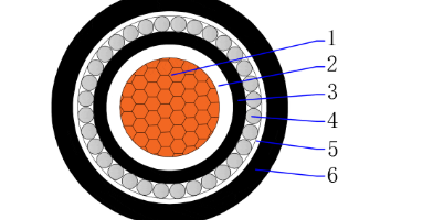
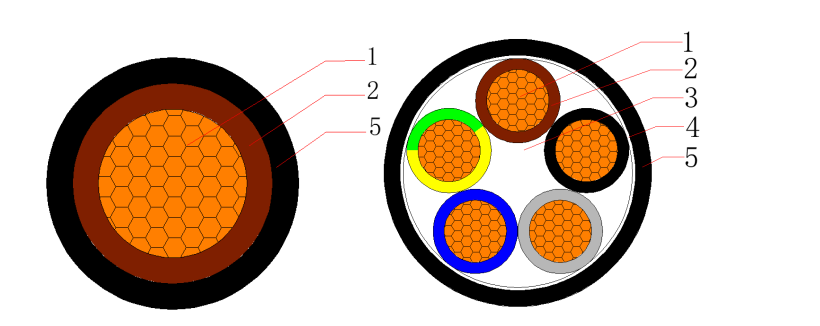
- 1. Conductor – Plain annealed class 2 stranded (compacted) copper
- 2. Insulation – Polyvinyl chloride compound (PVC)
- 3. Filler – Non-hygroscopic material
- 4. Binder tape – Non-hygroscopic material tape
- 5. Outer sheath – Polyvinyl chloride compound (PVC)
Cross Section:
- 1C1.5~800mm2
- 2C1.5~2C400mm2
- 3C1.5~3C400mm2
- 4C1.5~4C400mm2
- 5C1.5~5C400mm2
- 2C+E2.5~2C+E400mm2
- 3C+E2.5~3C+E400mm2
- 4C+E2.5~4C+E400mm2
Temperature characteristics:
- Conductor operating temperature: -15℃~70℃
- Min. temperatrue laying condition: 0℃
- Conductor short-circuit operating temperature (5s): 160℃(≤300mm2) 140℃(>300mm2)
Electrical Characteristics:
- Rated voltage: 0.6/1 (1.2) kV
- High voltage test: 3.5kV / 5min
Color:
- Insulation: According to customer requirements
- Outer sheath: Black or according to customer requirements
Minimum Bending Radius:
| Items | Single-core Cables | Three-core Cables | ||
| Unarmoured | Armoured | Unarmoured | Armoured | |
| Min. bending radius during installation | 20D | 15D | 15D | 12D |
| Min. bending radius close to connection box and termination (bending radius should be controlled carefully, if the molding guide plate is used) | 15D | 12D | 12D | 10D |
Applicable Standards
Optional
Technical Parameters
| No. of Cores and Nominal Cross Section | Min. Number of Wires | Nominal Insulation Thickness | Nominal Sheath Thickness | Approx. Overall Diameter | Approx. Weight | Max. D.C .Resistance of Conductor at 20℃ |
| No. × mm² | No. | mm | mm | mm | kg/km | Ω/km |
| 1×1.5 | 1 | 0.8 | 1.4 | 5.8 | 49 | 12.1 |
| 1×2.5 | 1 | 0.8 | 1.4 | 6.2 | 61 | 7.41 |
| 1×4 | 1 | 1 | 1.4 | 7 | 85 | 4.61 |
| 1×6 | 1 | 1 | 1.4 | 7.5 | 108 | 3.08 |
| 1×10 | 6 | 1 | 1.4 | 8.8 | 157 | 1.83 |
| 1×16 | 6 | 1 | 1.4 | 9.6 | 218 | 1.15 |
| 1×25 | 6 | 1.2 | 1.4 | 11.2 | 320 | 0.727 |
| 1×35 | 6 | 1.2 | 1.4 | 12.2 | 416 | 0.524 |
| 1×50 | 6 | 1.4 | 1.4 | 13.9 | 551 | 0.387 |
| 1×70 | 12 | 1.4 | 1.5 | 15.6 | 761 | 0.268 |
| 1×95 | 15 | 1.6 | 1.5 | 17.8 | 1030 | 0.193 |
| 1×120 | 18 | 1.6 | 1.6 | 19.4 | 1274 | 0.153 |
| 1×150 | 18 | 1.8 | 1.6 | 21.1 | 1554 | 0.124 |
| 1×185 | 30 | 2 | 1.7 | 23.4 | 1943 | 0.0991 |
| 1×240 | 34 | 2.2 | 1.8 | 26.3 | 2508 | 0.0754 |
| 1×300 | 34 | 2.4 | 1.9 | 29.1 | 3123 | 0.0601 |
| 1×400 | 53 | 2.6 | 2 | 32.4 | 3981 | 0.047 |
| 1×500 | 53 | 2.8 | 2.1 | 36.1 | 5014 | 0.0366 |
| 1×630 | 53 | 2.8 | 2.2 | 40 | 6392 | 0.0283 |
| No. of Cores and Nominal Cross Section | Min. Number of Wires | Nominal Insulation Thickness | Nominal Sheath Thickness | Approx. Overall Diameter | Approx. Weight | Max. D.C .Resistance of Conductor at 20℃ |
| No. × mm² | No. | mm | mm | mm | kg/km | Ω/km |
| 2×1.5 | 1 | 0.8 | 1.8 | 9.8 | 117 | 12.1 |
| 2×2.5 | 1 | 0.8 | 1.8 | 10.6 | 145 | 7.41 |
| 2×4 | 1 | 1 | 1.8 | 12.4 | 203 | 4.61 |
| 2×6 | 1 | 1 | 1.8 | 13.4 | 257 | 3.08 |
| 2×10 | 6 | 1 | 1.8 | 15.9 | 373 | 1.83 |
| 2×16 | 6 | 1 | 1.8 | 17.5 | 508 | 1.15 |
| 2×25 | 6 | 1.2 | 1.8 | 20.7 | 740 | 0.727 |
| 2×35 | 6 | 1.2 | 1.8 | 22.7 | 954 | 0.524 |
| 2×50 | 6 | 1.4 | 1.8 | 26.1 | 1264 | 0.387 |
| 2×70 | 12 | 1.4 | 1.9 | 29.6 | 1701 | 0.268 |
| 2×95 | 15 | 1.6 | 2 | 34.2 | 2311 | 0.193 |
| 2×120 | 18 | 1.6 | 2.1 | 37.2 | 2841 | 0.153 |
| 2×150 | 18 | 1.8 | 2.2 | 41.2 | 3486 | 0.124 |
| 2×185 | 30 | 2 | 2.4 | 45.6 | 4351 | 0.0991 |
| 2×240 | 34 | 2.2 | 2.6 | 51.4 | 5613 | 0.0754 |
| 2×300 | 34 | 2.4 | 2.7 | 56.8 | 6961 | 0.0601 |
| 2×400 | 53 | 2.6 | 3 | 63.8 | 8896 | 0.047 |
| No. of Cores and Nominal Cross Section | Min. Number of Wires | Nominal Insulation Thickness | Nominal Sheath Thickness | Approx. Overall Diameter | Approx. Weight | Max. D.C .Resistance of Conductor at 20℃ |
| No. × mm² | No. | mm | mm | mm | kg/km | Ω/km |
| 3×1.5 | 1 | 0.8 | 1.8 | 10.3 | 141 | 12.1 |
| 3×2.5 | 1 | 0.8 | 1.8 | 11.2 | 179 | 7.41 |
| 3×4 | 1 | 1 | 1.8 | 13 | 256 | 4.61 |
| 3×6 | 1 | 1 | 1.8 | 14.1 | 330 | 3.08 |
| 3×10 | 6 | 1 | 1.8 | 16.9 | 487 | 1.83 |
| 3×16 | 6 | 1 | 1.8 | 18.6 | 679 | 1.15 |
| 3×25 | 6 | 1.2 | 1.8 | 22 | 1000 | 0.727 |
| 3X35 | 6 | 1.2 | 1.8 | 24.2 | 1304 | 0.524 |
| 3×50 | 6 | 1.4 | 1.8 | 27.9 | 1735 | 0.387 |
| 3×70 | 12 | 1.4 | 2 | 31.8 | 2383 | 0.268 |
| 3×95 | 15 | 1.6 | 2.1 | 36.8 | 3248 | 0.193 |
| 3×120 | 18 | 1.6 | 2.2 | 40 | 4005 | 0.153 |
| 3×150 | 18 | 1.8 | 2.3 | 44.3 | 4919 | 0.124 |
| 3×185 | 30 | 2 | 2.5 | 49 | 6147 | 0.0991 |
| 3×240 | 34 | 2.2 | 2.7 | 55.2 | 7942 | 0.0754 |
| 3×300 | 34 | 2.4 | 2.9 | 61.3 | 9896 | 0.0601 |
| 3×400 | 53 | 2.6 | 3.1 | 68.6 | 12621 | 0.047 |
| No. of Cores and Nominal Cross Section | Min. Number of Wires | Nominal Insulation Thickness | Nominal Sheath Thickness | Approx. Overall Diameter | Approx. Weight | Max. D.C .Resistance of Conductor at 20℃ |
| No. × mm² | No. | mm | mm | mm | kg/km | Ω/km |
| 4×1.5 | 1 | 0.8 | 1.8 | 11.1 | 170 | 12.1 |
| 4×2.5 | 1 | 0.8 | 1.8 | 12 | 218 | 7.41 |
| 4×4 | 1 | 1 | 1.8 | 14.1 | 317 | 4.61 |
| 4×6 | 1 | 1 | 1.8 | 15.4 | 413 | 3.08 |
| 4×10 | 6 | 1 | 1.8 | 18.4 | 615 | 1.83 |
| 4×16 | 6 | 1 | 1.8 | 20.4 | 866 | 1.15 |
| 4×25 | 6 | 1.2 | 1.8 | 24.2 | 1284 | 0.727 |
| 4×35 | 6 | 1.2 | 1.8 | 26.6 | 1682 | 0.524 |
| 4×50 | 6 | 1.4 | 1.9 | 31.3 | 2268 | 0.387 |
| 4×70 | 12 | 1.4 | 2.1 | 35.3 | 3110 | 0.268 |
| 4×95 | 15 | 1.6 | 2.2 | 40.8 | 4245 | 0.193 |
| 4×120 | 18 | 1.6 | 2.3 | 44.4 | 5239 | 0.153 |
| 4×150 | 18 | 1.8 | 2.5 | 49.4 | 6460 | 0.124 |
| 4×185 | 30 | 2 | 2.7 | 54.6 | 8072 | 0.0991 |
| 4×240 | 34 | 2.2 | 2.9 | 61.6 | 10431 | 0.0754 |
| 4×300 | 34 | 2.4 | 3.1 | 68.3 | 12998 | 0.0601 |
| 4×400 | 53 | 2.6 | 3.4 | 76.6 | 16617 | 0.047 |
| No. of Cores and Nominal Cross Section | Min. Number of Wires | Nominal Insulation Thickness | Nominal Sheath Thickness | Approx. Overall Diameter | Approx. Weight | Max. D.C .Resistance of Conductor at 20℃ |
| No. × mm² | No. | mm | mm | mm | kg/km | Ω/km |
| 5×1.5 | 1 | 0.8 | 1.8 | 11.9 | 200 | 12.1 |
| 5×2.5 | 1 | 0.8 | 1.8 | 13 | 259 | 7.41 |
| 5×4 | 1 | 1 | 1.8 | 15.3 | 381 | 4.61 |
| 5×6 | 1 | 1 | 1.8 | 16.7 | 499 | 3.08 |
| 5×10 | 6 | 1 | 1.8 | 20.1 | 749 | 1.83 |
| 5×16 | 6 | 1 | 1.8 | 22.3 | 1060 | 1.15 |
| 5×25 | 6 | 1.2 | 1.8 | 26.6 | 1577 | 0.727 |
| 5×35 | 6 | 1.2 | 1.9 | 29.8 | 2093 | 0.524 |
| 5×50 | 6 | 1.4 | 2 | 34.6 | 2811 | 0.387 |
| 5×70 | 12 | 1.4 | 2.2 | 39 | 3857 | 0.268 |
| 5×95 | 15 | 1.6 | 2.4 | 45.4 | 5288 | 0.193 |
| 5×120 | 18 | 1.6 | 2.5 | 49.3 | 6526 | 0.153 |
| 5×150 | 18 | 1.8 | 2.7 | 54.9 | 8044 | 0.124 |
| 5×185 | 30 | 2 | 2.9 | 60.7 | 10048 | 0.0991 |
| 5×240 | 34 | 2.2 | 3.1 | 68.4 | 12983 | 0.0754 |
| 5×300 | 34 | 2.4 | 3.3 | 75.8 | 16177 | 0.0601 |
| 5×400 | 53 | 2.6 | 3.7 | 85.2 | 20715 | 0.047 |
| No. of Cores and Nominal Cross Section | Min. Number of Wires | Nominal Insulation Thickness | Nominal Sheath Thickness | Approx. Overall Diameter | Approx. Weight | Max. D.C .Resistance of Conductor at 20℃ |
| No. × mm² | No. | mm | mm | mm | kg/km | Ω/km |
| 3×2.5+1×1.5 | 1/1 | 0.8/0.8 | 1.8 | 11.8 | 206 | 7.41/12.1 |
| 3×4+1×2.5 | 1/1 | 1.0/0.8 | 1.8 | 13.6 | 292 | 4.61/7.41 |
| 3×6+1×4 | 1/1 | 1.0/1.0 | 1.8 | 15.1 | 389 | 3.08/4.61 |
| 3×10+1×6 | 6/1 | 1.0/1.0 | 1.8 | 17.7 | 564 | 1.83/3.08 |
| 3×16+1×10 | 6/6 | 1.0/1.0 | 1.8 | 19.9 | 803 | 1.15/1.83 |
| 3×25+1×16 | 6/6 | 1.2/1.0 | 1.8 | 23.3 | 1177 | 0.727/1.15 |
| 3×35+1×16 | 6/6 | 1.2/1.0 | 1.8 | 25.1 | 1474 | 0.524/1.15 |
| 3×50+1×25 | 6/6 | 1.4/1.2 | 1.9 | 29.6 | 2023 | 0.387/0.727 |
| 3×70+1×35 | 12/6 | 1.4/1.2 | 2 | 33.2 | 2741 | 0.268/0.524 |
| 3×95+1×50 | 15/6 | 1.6/1.4 | 2.2 | 38.6 | 3750 | 0.193/0.387 |
| 3×120+1×70 | 18/12 | 1.6/1.4 | 2.3 | 42.2 | 4710 | 0.153/0.268 |
| 3×150+1×70 | 18/12 | 1.8/1.4 | 2.4 | 45.9 | 5606 | 0.124/0.268 |
| 3×185+1×95 | 30/15 | 2.0/1.6 | 2.6 | 51.2 | 7104 | 0.0991/0.193 |
| 3×240+1×120 | 34/18 | 2.2/1.6 | 2.8 | 57.4 | 9120 | 0.0754/0.153 |
| 3×300+1×150 | 34/18 | 2.4/1.8 | 3 | 63.7 | 11347 | 0.0601/0.124 |
| 3×400+1×185 | 53/30 | 2.6/2.0 | 3.2 | 71.1 | 14431 | 0.0470/0.0991 |
| No. of Cores and Nominal Cross Section | Min. Number of Wires | Nominal Insulation Thickness | Nominal Sheath Thickness | Approx. Overall Diameter | Approx. Weight | Max. D.C .Resistance of Conductor at 20℃ |
| No. × mm² | No. | mm | mm | mm | kg/km | Ω/km |
| 3×2.5+2×1.5 | 1/1 | 0.8/0.8 | 1.8 | 12.5 | 235 | 7.41/12.1 |
| 3×4+2×2.5 | 1/1 | 1.0/0.8 | 1.8 | 14.4 | 331 | 4.61/7.41 |
| 3×6+2×4 | 1/1 | 1.0/1.0 | 1.8 | 16.1 | 451 | 3.08/4.61 |
| 3×10+2×6 | 6/1 | 1.0/1.0 | 1.8 | 18.7 | 647 | 1.83/3.08 |
| 3×16+2×10 | 6/6 | 1.0/1.0 | 1.8 | 21.4 | 935 | 1.15/1.83 |
| 3×25+2×16 | 6/6 | 1.2/1.0 | 1.8 | 24.9 | 1366 | 0.727/1.15 |
| 3×35+2×16 | 6/6 | 1.2/1.0 | 1.8 | 26.5 | 1660 | 0.524/1.15 |
| 3×50+2×25 | 6/6 | 1.4/1.2 | 1.9 | 31.5 | 2310 | 0.387/0.727 |
| 3×70+2×35 | 12/6 | 1.4/1.2 | 2.1 | 35.4 | 3138 | 0.268/0.524 |
| 3×95+2×50 | 15/6 | 1.6/1.4 | 2.2 | 41 | 4266 | 0.193/0.387 |
| 3×120+2×70 | 18/12 | 1.6/1.4 | 2.4 | 45.3 | 5451 | 0.153/0.268 |
| 3×150+2×70 | 18/12 | 1.8/1.4 | 2.5 | 48.5 | 6341 | 0.124/0.268 |
| 3×185+2×95 | 30/15 | 2.0/1.6 | 2.7 | 54.5 | 8118 | 0.0991/0.193 |
| 3×240+2×120 | 34/18 | 2.2/1.6 | 2.9 | 60.8 | 10371 | 0.0754/0.153 |
| 3×300+2×150 | 34/18 | 2.4/1.8 | 3.1 | 67.5 | 12889 | 0.0601/0.124 |
| 3×400+2×185 | 53/30 | 2.6/2.0 | 3.3 | 75.2 | 16355 | 0.0470/0.0991 |
| No. of Cores and Nominal Cross Section | Min. Number of Wires | Nominal Insulation Thickness | Nominal Sheath Thickness | Approx. Overall Diameter | Approx. Weight | Max. D.C .Resistance of Conductor at 20℃ |
| No. × mm² | No. | mm | mm | mm | kg/km | Ω/km |
| 4×2.5+1×1.5 | 1/1 | 0.8/0.8 | 1.8 | 12.8 | 247 | 7.41/12.1 |
| 4×4+1×2.5 | 1/1 | 1.0/0.8 | 1.8 | 14.9 | 356 | 4.61/7.41 |
| 4×6+1×4 | 1/1 | 1.0/1.0 | 1.8 | 16.4 | 475 | 3.08/4.61 |
| 4×10+1×6 | 6/1 | 1.0/1.0 | 1.8 | 19.4 | 698 | 1.83/3.08 |
| 4×16+1×10 | 6/6 | 1.0/1.0 | 1.8 | 21.8 | 997 | 1.15/1.83 |
| 4×25+1×16 | 6/6 | 1.2/1.0 | 1.8 | 25.7 | 1471 | 0.727/1.15 |
| 4×35+1×16 | 6/6 | 1.2/1.0 | 1.8 | 27.9 | 1865 | 0.524/1.15 |
| 4×50+1×25 | 6/6 | 1.4/1.2 | 2 | 33.1 | 2567 | 0.387/0.727 |
| 4×70+1×35 | 12/6 | 1.4/1.2 | 2.1 | 37.1 | 3487 | 0.268/0.524 |
| 4×95+1×50 | 15/6 | 1.6/1.4 | 2.3 | 43.2 | 4775 | 0.193/0.387 |
| 4×120+1×70 | 18/12 | 1.6/1.4 | 2.4 | 47.2 | 5976 | 0.153/0.268 |
| 4×150+1×70 | 18/12 | 1.8/1.4 | 2.6 | 51.7 | 7188 | 0.124/0.268 |
| 4×185+1×95 | 30/15 | 2.0/1.6 | 2.8 | 57.6 | 9079 | 0.0991/0.193 |
| 4×240+1×120 | 34/18 | 2.2/1.6 | 3 | 64.6 | 11671 | 0.0754/0.153 |
| 4×300+1×150 | 34/18 | 2.4/1.8 | 3.2 | 71.6 | 14525 | 0.0601/0.124 |
| 4×400+1×185 | 53/30 | 2.6/2.0 | 3.5 | 80.2 | 18523 | 0.0470/0.0991 |
FAQ
In the electric cabling lettering system, NYY cable specification refers to the following: N = Means the cables have a copper core. Y = Means the cable has an inner PVC insulation; and. Y = Refers to outer PVC insulation.
A 0.6/1kV cable is a low-voltage electrical power cable. The rating indicates that the cable is designed to safely handle up to 0.6 kV (600 volts) between the conductor and the earth/ground, and up to 1 kV (1000 volts) between two phase conductors.
XThe primary difference lies in the insulation material. N2XY uses XLPE (Cross-linked Polyethylene), which allows for a maximum conductor temperature of 90°C. NYY uses standard PVC insulation, which is limited to 70°C.
PVC vs XLPE for insulating cable: What’s the difference?
However, if a higher conductor temperature is required, causing the cable to rise above 70°C, then the cable chosen for this application should be insulated with XLPE.
This is because PVC has a maximum working temperature of 70°C which is exactly what is needed for standing building cables, whilst XLPE has a maximum working temperature of 90°C. Cables that are insulated with XLPE can run a higher current in the conductors.
Application of NYY Cable
NYY cables can be installed in the open air, underground, underwater, and indoors in areas protected from mechanical damage. This cable is UV-resistant and can be used outdoors.
Are PVC cables good?
It is widely used due to its elasticity and security features and also its sturdy resistance to heat and chemicals. Here’s the reason PVC cable is an increasingly popular choice: Installation is simple and easy to do. Resistant to flames and heat.