N2XH 0.6/1kV Single or Multicore unarmored cable
Single or Multicore XLPE insulated LSHF sheathed unarmored cable with copper conductor
Application:
To be used for main power supply, In low voltage distribution power networks, industrial installations, in buildings and operation stations. fixed installation in the ground or in concrete, in the cable trenches or cable, ducts, indoor or outdoor areas, in dry or wet locations.
Standard:
- Cable design: IEC 60502-1
- Conductor: IEC 60228
Construction
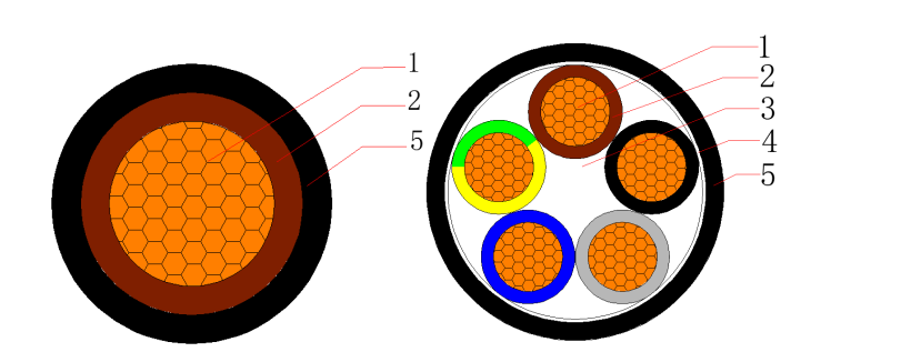
- 1. Conductor – Plain annealed class 2 stranded (compacted) copper
- 2. Insulation – Cross linked polyethylene (XLPE)
- 3. Filler – Non-hygroscopic material
- 4. Binder tape – Non-hygroscopic material tape
- 5. Outer sheath – Low smoke halogen-free flame retardant polyolefin compound (LSHF)
Cross Section:
- 1C1.5~800mm2
- 2C1.5~2C400mm2
- 3C1.5~3C400mm2
- 4C1.5~4C400mm2
- 5C1.5~5C400mm2
- 2C+E2.5~2C+E400mm2
- 3C+E2.5~3C+E400mm2
- 4C+E2.5~4C+E400mm2
Temperature characteristics:
- Conductor operating temperature: -15℃~90℃
- Min. temperatrue laying condition: 0℃
- Conductor short-circuit operating temperature (5s): 250℃
Electrical Characteristics:
- Rated voltage: 0.6/1 (1.2) kV
- High voltage test: 3.5kV / 5min
Color:
- Insulation: According to customer requirements
- Outer sheath: Black or according to customer requirements
Minimum Bending Radius:
| Items | Single-core Cables | Three-core Cables | ||
| Unarmoured | Armoured | Unarmoured | Armoured | |
| Min. bending radius during installation | 20D | 15D | 15D | 12D |
| Min. bending radius close to connection box and termination (bending radius should be controlled carefully, if the molding guide plate is used) | 15D | 12D | 12D | 10D |
Applicable Standards
Optional
Technical Parameters
| No. of Cores and Nominal Cross Section | Min. Number of Wires | Nominal Insulation Thickness | Nominal Sheath Thickness | Approx. Overall Diameter | Approx. Weight | Max. D.C .Resistance of Conductor at 20℃ |
| No. × mm² | No. | mm | mm | mm | kg/km | Ω/km |
| 1×1.5 | 1 | 0.7 | 1.4 | 5.6 | 44 | 12.1 |
| 1×2.5 | 1 | 0.7 | 1.4 | 6 | 55 | 7.41 |
| 1×4 | 1 | 0.7 | 1.4 | 6.4 | 72 | 4.61 |
| 1×6 | 1 | 0.7 | 1.4 | 6.9 | 95 | 3.08 |
| 1×10 | 6 | 0.7 | 1.4 | 8.2 | 140 | 1.83 |
| 1×16 | 6 | 0.7 | 1.4 | 9 | 199 | 1.15 |
| 1×25 | 6 | 0.9 | 1.4 | 10.6 | 295 | 0.727 |
| 1×35 | 6 | 0.9 | 1.4 | 11.6 | 389 | 0.524 |
| 1×50 | 6 | 1 | 1.4 | 13.1 | 512 | 0.387 |
| 1×70 | 12 | 1.1 | 1.4 | 14.8 | 714 | 0.268 |
| 1×95 | 15 | 1.1 | 1.5 | 16.8 | 968 | 0.193 |
| 1×120 | 18 | 1.2 | 1.5 | 18.4 | 1204 | 0.153 |
| 1×150 | 18 | 1.4 | 1.6 | 20.5 | 1484 | 0.124 |
| 1×185 | 30 | 1.6 | 1.6 | 22.5 | 1847 | 0.0991 |
| 1×240 | 34 | 1.7 | 1.7 | 25.2 | 2385 | 0.0754 |
| 1×300 | 34 | 1.8 | 1.8 | 27.8 | 2970 | 0.0601 |
| 1×400 | 53 | 2 | 1.9 | 31.2 | 3803 | 0.047 |
| 1×500 | 53 | 2.2 | 2 | 34.7 | 4801 | 0.0366 |
| 1×630 | 53 | 2.4 | 2.2 | 39.2 | 6196 | 0.0283 |
| No. of Cores and Nominal Cross Section | Min. Number of Wires | Nominal Insulation Thickness | Nominal Sheath Thickness | Approx. Overall Diameter | Approx. Weight | Max. D.C .Resistance of Conductor at 20℃ |
| No. × mm² | No. | mm | mm | mm | kg/km | Ω/km |
| 2×1.5 | 1 | 0.7 | 1.8 | 9.4 | 105 | 12.1 |
| 2×2.5 | 1 | 0.7 | 1.8 | 10.2 | 132 | 7.41 |
| 2×4 | 1 | 0.7 | 1.8 | 11.2 | 172 | 4.61 |
| 2×6 | 1 | 0.7 | 1.8 | 12.2 | 222 | 3.08 |
| 2×10 | 6 | 0.7 | 1.8 | 14.7 | 330 | 1.83 |
| 2×16 | 6 | 0.7 | 1.8 | 16.3 | 461 | 1.15 |
| 2×25 | 6 | 0.9 | 1.8 | 19.5 | 679 | 0.727 |
| 2×35 | 6 | 0.9 | 1.8 | 21.5 | 886 | 0.524 |
| 2×50 | 6 | 1 | 1.8 | 24.5 | 1166 | 0.387 |
| 2×70 | 12 | 1.1 | 1.8 | 27.9 | 1587 | 0.268 |
| 2×95 | 15 | 1.1 | 2 | 32.2 | 2161 | 0.193 |
| 2×120 | 18 | 1.2 | 2.1 | 35.6 | 2694 | 0.153 |
| 2×150 | 18 | 1.4 | 2.2 | 39.6 | 3312 | 0.124 |
| 2×185 | 30 | 1.6 | 2.3 | 43.8 | 4127 | 0.0991 |
| 2×240 | 34 | 1.7 | 2.5 | 49.2 | 5322 | 0.0754 |
| 2×300 | 34 | 1.8 | 2.7 | 54.4 | 6622 | 0.0601 |
| 2×400 | 53 | 2 | 2.9 | 61.2 | 8470 | 0.047 |
| No. of Cores and Nominal Cross Section | Min. Number of Wires | Nominal Insulation Thickness | Nominal Sheath Thickness | Approx. Overall Diameter | Approx. Weight | Max. D.C .Resistance of Conductor at 20℃ |
| No. × mm² | No. | mm | mm | mm | kg/km | Ω/km |
| 3×1.5 | 1 | 0.7 | 1.8 | 9.9 | 126 | 12.1 |
| 3×2.5 | 1 | 0.7 | 1.8 | 10.7 | 161 | 7.41 |
| 3×4 | 1 | 0.7 | 1.8 | 11.7 | 216 | 4.61 |
| 3×6 | 1 | 0.7 | 1.8 | 12.8 | 285 | 3.08 |
| 3×10 | 6 | 0.7 | 1.8 | 15.6 | 432 | 1.83 |
| 3×16 | 6 | 0.7 | 1.8 | 17.3 | 617 | 1.15 |
| 3×25 | 6 | 0.9 | 1.8 | 20.7 | 918 | 0.727 |
| 3X35 | 6 | 0.9 | 1.8 | 22.9 | 1213 | 0.524 |
| 3×50 | 6 | 1 | 1.8 | 26.1 | 1605 | 0.387 |
| 3×70 | 12 | 1.1 | 1.9 | 30.3 | 2240 | 0.268 |
| 3×95 | 15 | 1.1 | 2 | 34.4 | 3028 | 0.193 |
| 3×120 | 18 | 1.2 | 2.1 | 38.1 | 3786 | 0.153 |
| 3×150 | 18 | 1.4 | 2.3 | 42.6 | 4679 | 0.124 |
| 3×185 | 30 | 1.6 | 2.4 | 47.1 | 5842 | 0.0991 |
| 3×240 | 34 | 1.7 | 2.6 | 52.9 | 7547 | 0.0754 |
| 3×300 | 34 | 1.8 | 2.8 | 58.5 | 9400 | 0.0601 |
| 3×400 | 53 | 2 | 3.1 | 66 | 12068 | 0.047 |
| No. of Cores and Nominal Cross Section | Min. Number of Wires | Nominal Insulation Thickness | Nominal Sheath Thickness | Approx. Overall Diameter | Approx. Weight | Max. D.C .Resistance of Conductor at 20℃ |
| No. × mm² | No. | mm | mm | mm | kg/km | Ω/km |
| 4×1.5 | 1 | 0.7 | 1.8 | 10.6 | 150 | 12.1 |
| 4×2.5 | 1 | 0.7 | 1.8 | 11.5 | 196 | 7.41 |
| 4×4 | 1 | 0.7 | 1.8 | 12.7 | 266 | 4.61 |
| 4×6 | 1 | 0.7 | 1.8 | 13.9 | 356 | 3.08 |
| 4×10 | 6 | 0.7 | 1.8 | 17 | 545 | 1.83 |
| 4×16 | 6 | 0.7 | 1.8 | 18.9 | 787 | 1.15 |
| 4×25 | 6 | 0.9 | 1.8 | 22.8 | 1179 | 0.727 |
| 4×35 | 6 | 0.9 | 1.8 | 25.2 | 1565 | 0.524 |
| 4×50 | 6 | 1 | 1.9 | 29 | 2090 | 0.387 |
| 4×70 | 12 | 1.1 | 2 | 33.6 | 2926 | 0.268 |
| 4×95 | 15 | 1.1 | 2.1 | 38.2 | 3962 | 0.193 |
| 4×120 | 18 | 1.2 | 2.3 | 42.5 | 4976 | 0.153 |
| 4×150 | 18 | 1.4 | 2.4 | 47.3 | 6125 | 0.124 |
| 4×185 | 30 | 1.6 | 2.6 | 52.5 | 7677 | 0.0991 |
| 4×240 | 34 | 1.7 | 2.8 | 59 | 9918 | 0.0754 |
| 4×300 | 34 | 1.8 | 3 | 65.2 | 12355 | 0.0601 |
| 4×400 | 53 | 2 | 3.3 | 73.5 | 15859 | 0.047 |
| No. of Cores and Nominal Cross Section | Min. Number of Wires | Nominal Insulation Thickness | Nominal Sheath Thickness | Approx. Overall Diameter | Approx. Weight | Max. D.C .Resistance of Conductor at 20℃ |
| No. × mm² | No. | mm | mm | mm | kg/km | Ω/km |
| 5×1.5 | 1 | 0.7 | 1.8 | 11.4 | 176 | 12.1 |
| 5×2.5 | 1 | 0.7 | 1.8 | 12.4 | 232 | 7.41 |
| 5×4 | 1 | 0.7 | 1.8 | 13.7 | 318 | 4.61 |
| 5×6 | 1 | 0.7 | 1.8 | 15.1 | 430 | 3.08 |
| 5×10 | 6 | 0.7 | 1.8 | 18.5 | 662 | 1.83 |
| 5×16 | 6 | 0.7 | 1.8 | 20.6 | 962 | 1.15 |
| 5×25 | 6 | 0.9 | 1.8 | 25 | 1448 | 0.727 |
| 5×35 | 6 | 0.9 | 1.8 | 27.7 | 1928 | 0.524 |
| 5×50 | 6 | 1 | 2 | 32.4 | 2600 | 0.387 |
| 5×70 | 12 | 1.1 | 2.1 | 37.2 | 3630 | 0.268 |
| 5×95 | 15 | 1.1 | 2.3 | 42.5 | 4938 | 0.193 |
| 5×120 | 18 | 1.2 | 2.4 | 47 | 6177 | 0.153 |
| 5×150 | 18 | 1.4 | 2.6 | 52.5 | 7629 | 0.124 |
| 5×185 | 30 | 1.6 | 2.8 | 58.3 | 9559 | 0.0991 |
| 5×240 | 34 | 1.7 | 3 | 65.5 | 12348 | 0.0754 |
| 5×300 | 34 | 1.8 | 3.2 | 72.3 | 15381 | 0.0601 |
| 5×400 | 53 | 2 | 3.6 | 81.8 | 19775 | 0.047 |
| No. of Cores and Nominal Cross Section | Min. Number of Wires | Nominal Insulation Thickness | Nominal Sheath Thickness | Approx. Overall Diameter | Approx. Weight | Max. D.C .Resistance of Conductor at 20℃ |
| No. × mm² | No. | mm | mm | mm | kg/km | Ω/km |
| 3×2.5+1×1.5 | 1/1 | 0.7/0.7 | 1.8 | 11.3 | 184 | 7.41/12.1 |
| 3×4+1×2.5 | 1/1 | 0.7/0.7 | 1.8 | 12.4 | 248 | 4.61/7.41 |
| 3×6+1×4 | 1/1 | 0.7/0.7 | 1.8 | 13.6 | 334 | 3.08/4.61 |
| 3×10+1×6 | 6/1 | 0.7/0.7 | 1.8 | 16.2 | 497 | 1.83/3.08 |
| 3×16+1×10 | 6/6 | 0.7/0.7 | 1.8 | 18.4 | 726 | 1.15/1.83 |
| 3×25+1×16 | 6/6 | 0.9/0.7 | 1.8 | 21.8 | 1079 | 0.727/1.15 |
| 3×35+1×16 | 6/6 | 0.9/0.7 | 1.8 | 23.6 | 1366 | 0.524/1.15 |
| 3×50+1×25 | 6/6 | 1.0/0.9 | 1.8 | 27.3 | 1849 | 0.387/0.727 |
| 3×70+1×35 | 12/6 | 1.1/0.9 | 1.9 | 31.5 | 2572 | 0.268/0.524 |
| 3×95+1×50 | 15/6 | 1.1/1.0 | 2.1 | 36.1 | 3494 | 0.193/0.387 |
| 3×120+1×70 | 18/12 | 1.2/1.1 | 2.2 | 40.2 | 4452 | 0.153/0.268 |
| 3×150+1×70 | 18/12 | 1.4/1.1 | 2.3 | 43.9 | 5309 | 0.124/0.268 |
| 3×185+1×95 | 30/15 | 1.6/1.1 | 2.5 | 49 | 6736 | 0.0991/0.193 |
| 3×240+1×120 | 34/18 | 1.7/1.2 | 2.7 | 54.9 | 8666 | 0.0754/0.153 |
| 3×300+1×150 | 34/18 | 1.8/1.4 | 2.9 | 60.8 | 10783 | 0.0601/0.124 |
| 3×400+1×185 | 53/30 | 2.0/1.6 | 3.1 | 68.2 | 13768 | 0.0470/0.0991 |
| No. of Cores and Nominal Cross Section | Min. Number of Wires | Nominal Insulation Thickness | Nominal Sheath Thickness | Approx. Overall Diameter | Approx. Weight | Max. D.C .Resistance of Conductor at 20℃ |
| No. × mm² | No. | mm | mm | mm | kg/km | Ω/km |
| 3×2.5+2×1.5 | 1/1 | 0.7/0.7 | 1.8 | 12 | 210 | 7.41/12.1 |
| 3×4+2×2.5 | 1/1 | 0.7/0.7 | 1.8 | 13.2 | 284 | 4.61/7.41 |
| 3×6+2×4 | 1/1 | 0.7/0.7 | 1.8 | 14.5 | 385 | 3.08/4.61 |
| 3×10+2×6 | 6/1 | 0.7/0.7 | 1.8 | 17.1 | 568 | 1.83/3.08 |
| 3×16+2×10 | 6/6 | 0.7/0.7 | 1.8 | 19.8 | 841 | 1.15/1.83 |
| 3×25+2×16 | 6/6 | 0.9/0.7 | 1.8 | 23.2 | 1250 | 0.727/1.15 |
| 3×35+2×16 | 6/6 | 0.9/0.7 | 1.8 | 24.9 | 1535 | 0.524/1.15 |
| 3×50+2×25 | 6/6 | 1.0/0.9 | 1.9 | 29.5 | 2133 | 0.387/0.727 |
| 3×70+2×35 | 12/6 | 1.1/0.9 | 2 | 35.2 | 3198 | 0.268/0.524 |
| 3×95+2×50 | 15/6 | 1.1/1.0 | 2.2 | 38.5 | 3987 | 0.193/0.387 |
| 3×120+2×70 | 18/12 | 1.2/1.1 | 2.3 | 43.1 | 5152 | 0.153/0.268 |
| 3×150+2×70 | 18/12 | 1.4/1.1 | 2.4 | 46.4 | 6003 | 0.124/0.268 |
| 3×185+2×95 | 30/15 | 1.6/1.1 | 2.6 | 52 | 7683 | 0.0991/0.193 |
| 3×240+2×120 | 34/18 | 1.7/1.2 | 2.8 | 58.1 | 9853 | 0.0754/0.153 |
| 3×300+2×150 | 34/18 | 1.8/1.4 | 3 | 64.5 | 12249 | 0.0601/0.124 |
| 3×400+2×185 | 53/30 | 2.0/1.6 | 3.2 | 72.2 | 15602 | 0.0470/0.0991 |
| No. of Cores and Nominal Cross Section | Min. Number of Wires | Nominal Insulation Thickness | Nominal Sheath Thickness | Approx. Overall Diameter | Approx. Weight | Max. D.C .Resistance of Conductor at 20℃ |
| No. × mm² | No. | mm | mm | mm | kg/km | Ω/km |
| 4×2.5+1×1.5 | 1/1 | 0.7/0.7 | 1.8 | 12.2 | 221 | 7.41/12.1 |
| 4×4+1×2.5 | 1/1 | 0.7/0.7 | 1.8 | 13.4 | 301 | 4.61/7.41 |
| 4×6+1×4 | 1/1 | 0.7/0.7 | 1.8 | 14.8 | 407 | 3.08/4.61 |
| 4×10+1×6 | 6/1 | 0.7/0.7 | 1.8 | 17.8 | 615 | 1.83/3.08 |
| 4×16+1×10 | 6/6 | 0.7/0.7 | 1.8 | 20.2 | 902 | 1.15/1.83 |
| 4×25+1×16 | 6/6 | 0.9/0.7 | 1.8 | 24.1 | 1349 | 0.727/1.15 |
| 4×35+1×16 | 6/6 | 0.9/0.7 | 1.8 | 26.3 | 1730 | 0.524/1.15 |
| 4×50+1×25 | 6/6 | 1.0/0.9 | 1.9 | 30.9 | 2359 | 0.387/0.727 |
| 4×70+1×35 | 12/6 | 1.1/0.9 | 2.1 | 35.5 | 3291 | 0.268/0.524 |
| 4×95+1×50 | 15/6 | 1.1/1.0 | 2.2 | 40.4 | 4452 | 0.193/0.387 |
| 4×120+1×70 | 18/12 | 1.2/1.1 | 2.4 | 45.1 | 5673 | 0.153/0.268 |
| 4×150+1×70 | 18/12 | 1.4/1.1 | 2.5 | 49.4 | 6812 | 0.124/0.268 |
| 4×185+1×95 | 30/15 | 1.6/1.1 | 2.7 | 55.1 | 8617 | 0.0991/0.193 |
| 4×240+1×120 | 34/18 | 1.7/1.2 | 2.9 | 61.8 | 11095 | 0.0754/0.153 |
| 4×300+1×150 | 34/18 | 1.8/1.4 | 3.1 | 68.4 | 13808 | 0.0601/0.124 |
| 4×400+1×185 | 53/30 | 2.0/1.6 | 3.4 | 77 | 17677 | 0.0470/0.0991 |
FAQ
An N2XH cable is a halogen-free, flame-retardant power cable used for low-voltage electrical installations (typically 0.6/1 kV). It is specifically engineered for high-risk public and commercial spaces to protect human life and sensitive equipment from toxic smoke and corrosive gases during a fire.
N: Denotes it is a standard national cable (originally based on German VDE standards).
2X: Indicates Cross-Linked Polyethylene (XLPE) insulation. This provides excellent heat resistance and a higher continuous operating temperature (up to 90°C).
H: Indicates a Low Smoke Zero Halogen (LSZH) outer sheath. In the event of a fire, this material limits the spread of flames and prevents the emission of dense, toxic, or corrosive gases.
However, a key limitation of PVC cable properties is their thermal and chemical resistance. PVC cable temperature rating tyA 0.6/1kV cable is a low-voltage electrical power cable. The rating indicates that the cable is designed to safely handle up to 0.6 kV (600 volts) between the conductor and the earth/ground, and up to 1 kV (1000 volts) between two phase conductors.
Budget Constraints: If cost is a major concern, PVC cables might be the better option. Safety Requirements: For applications where fire safety is critical, LSZH cables are the preferred choice. Environmental Priorities: If reducing your environmental footprint is important, LSZH cables are more eco-friendly.
PVC vs XLPE for insulating cable: What’s the difference?
However, if a higher conductor temperature is required, causing the cable to rise above 70°C, then the cable chosen for this application should be insulated with XLPE.
This is because PVC has a maximum working temperature of 70°C which is exactly what is needed for standing building cables, whilst XLPE has a maximum working temperature of 90°C. Cables that are insulated with XLPE can run a higher current in the conductors.
XLPE (cross-linked polyethylene) cables offer excellent thermal and electrical performance, but their primary disadvantages include a higher initial cost (30%-50% more than PVC), increased rigidity that limits their bending radius, and high susceptibility to physical damage from impact or abrasion during routing.
Usually, the lifetime for XLPE is expected to be between 40 and 60 years at 90 °C rated operating temperature [14]. In this study, the estimated cable lifetime is 7–30 years at a rated operating temperature of 95–105 °C. Table 6 summaries the findings of cable lifetime in years for XLPE materials A and B.