Application
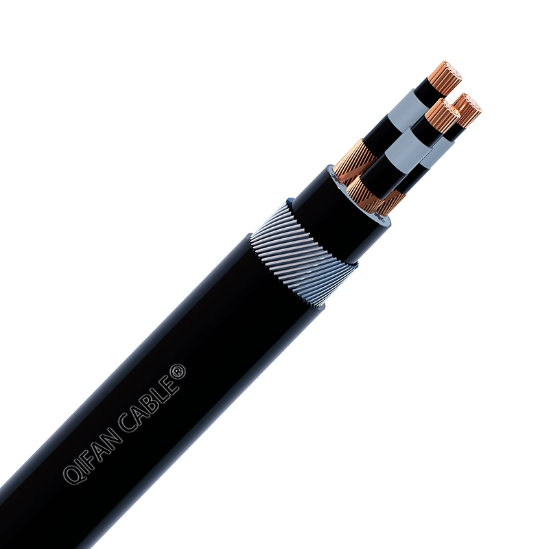
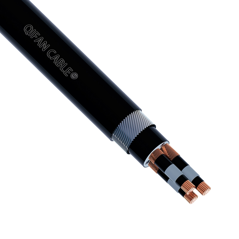
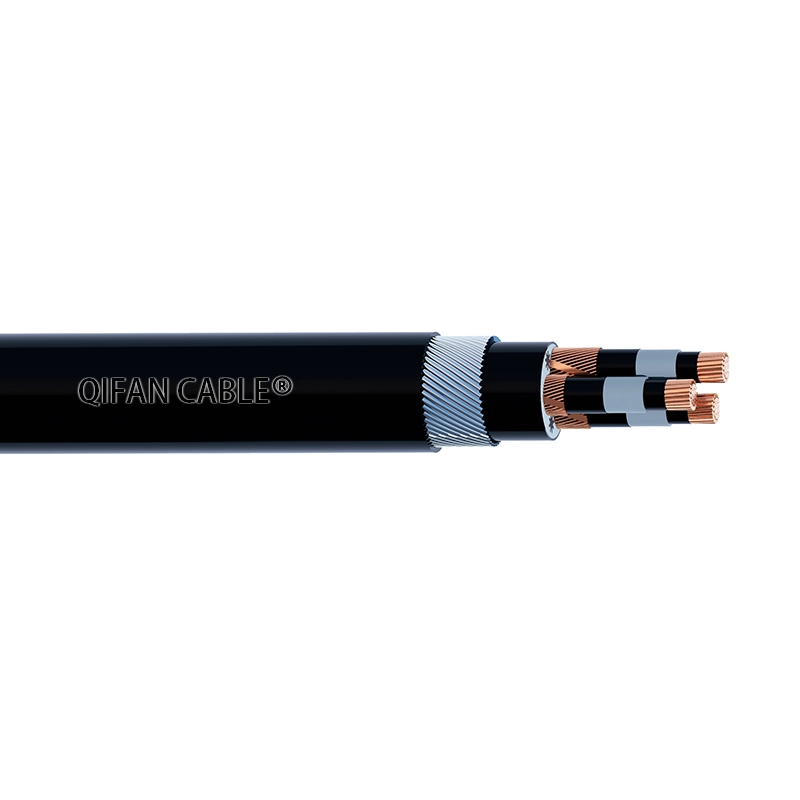
To be used for power distribution in medium voltage, as transformer feeders in substations. In power plants, industrial and operation installations, in residential areas and mining installations, in dry or wet locations, fixed installed in air, directly buried in the ground or in ducts, where require higher mechanical protection.
Characteristics
Electrical Characteristics:
Rated voltage: 3.8/6.6(7.2) kV
AC High voltage test: 12.5kV for 5min
Partial Discharge at 2 U0: ≤20PC or 1.5U0: ≤5PC
Temperature characteristics:
Conductor operating temperature: -15℃~90℃
Min. temperatrue laying condition: 0℃
Conductor emergency operating temperature: 105℃
Conductor short-circuit operating temperature (5s): 250℃
Color:
Core identification: Nature or Red、White、Blue color tape for three cores
Outer sheath: Black or according to customer requirements
Cross Section:
1 core; 25~1000mm2
3 core; 25~400mm2
Construction
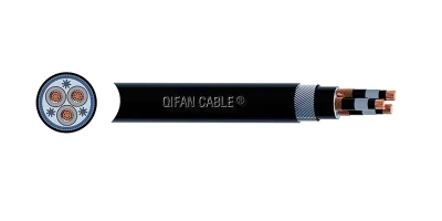
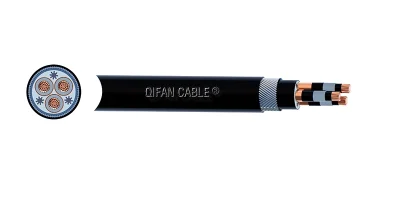
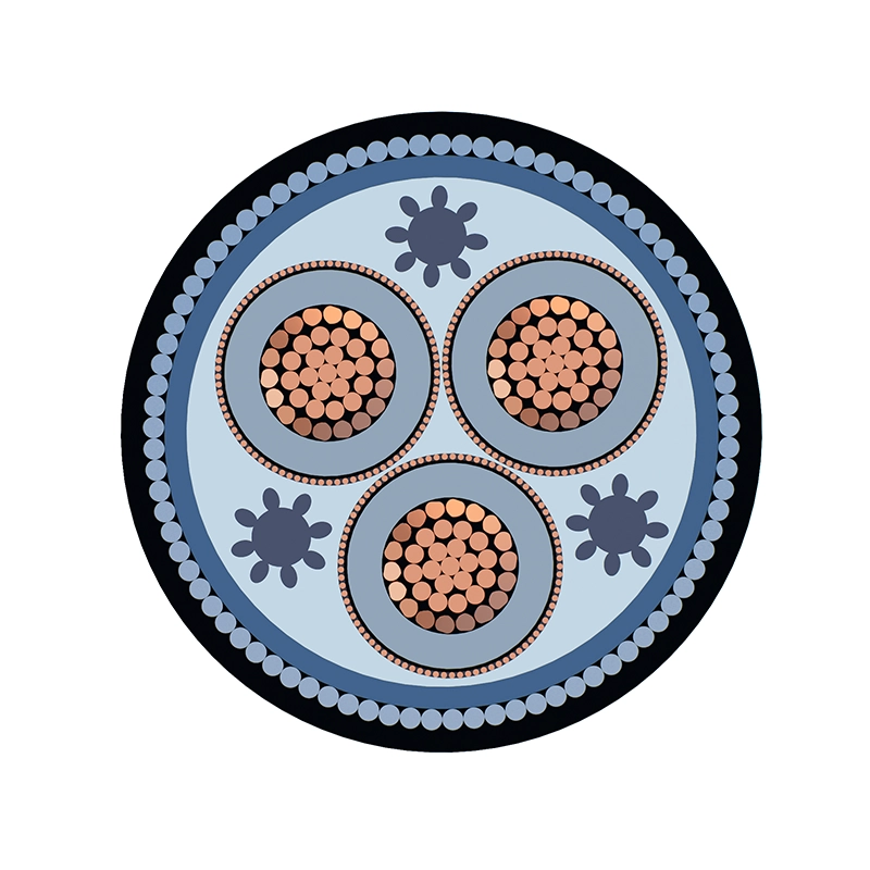
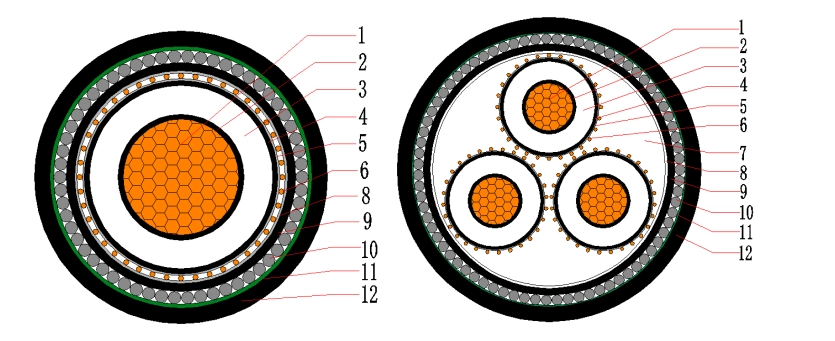
Construction:
- Conductor – Plain annealed class 2 compacted copper
- Conductor screen – Semi-conductive compound
- Insulation – Cross linked polyethylene (XLPE)
- Insulation screen – Semi-conductive compound
- Metallic screen – Plain annealed copper wire
- PP rope filler
- Binder tape – Non-hygroscopic material tape
- Separation layer – Polyvinyl chloride compound (PVC 5V-90)
- Armor – Hard drawn aluminum wires for single core or Galvanized steel wire for multi core
- Binder tape – Non-hygroscopic material tape
- Outer sheath – Polyvinyl chloride compound (PVC 5V-90)
Option for anti-termite : Nylon / PA12: Polyamide 12 anti-termite sheath
NOTE :The anti-termite nylon (PA12) sheath is an enhanced engineering structure, not a mandatory standard configuration.
Cable Drawing :
Applicable Standards
Optional
Technical Parameters
Dimensions
Single Core
| Nominal conductor area | mm² | 25 | 35 | 50 | 70 | 95 | 120 | 150 | 185 | 240 | 300 | 400 | 500 | 630 |
| Conductor diameter | mm | 6.0 | 7.0 | 8.2 | 10.0 | 11.6 | 13.0 | 14.6 | 16.2 | 18.4 | 20.6 | 23.4 | 26.6 | 30.0 |
| Nominal insulation thickness | mm | 2.5 | 2.5 | 2.5 | 2.5 | 2.5 | 2.5 | 2.5 | 2.5 | 2.6 | 2.8 | 3.0 | 2.2 | 2.4 |
| Nominal insulation diameter | mm | 12.6 | 13.6 | 14.8 | 16.6 | 18.2 | 19.6 | 21.2 | 22.8 | 25.2 | 27.8 | 31.0 | 32.5 | 36.3 |
| Nominal screen area on each core | mm² | 24.4 | 34.4 | 48.7 | 68.1 | 68.1 | 68.7 | 68.7 | 68.7 | 68.7 | 68.7 | 68.7 | 68.7 | 68.7 |
| Approx cable diameter | mm | 27.8 | 29.8 | 31.0 | 33.7 | 35.3 | 36.2 | 38.8 | 40.4 | 43.0 | 45.8 | 50.4 | 52.1 | 56.3 |
| Approx weight | kg/km | 1149 | 1395 | 1681 | 2156 | 2452 | 2728 | 3152 | 3534 | 4178 | 4857 | 5967 | 6977 | 8470 |
| Min. bending radius of duringinstallation | mm | 540 | 580 | 610 | 660 | 690 | 710 | 760 | 790 | 840 | 900 | 980 | 1020 | 1100 |
| Min. bending radius of after installation | mm | 360 | 390 | 410 | 440 | 460 | 470 | 510 | 530 | 560 | 600 | 660 | 680 | 730 |
| Max. pulling tension of conductor | kN | 1.7 | 2.4 | 3.4 | 4.8 | 6.5 | 8.2 | 10.2 | 12.6 | 16.4 | 20.4 | 27.2 | 34.0 | 42.9 |
| Max. DC. Resistance of conductor at 20 ℃ | ohm/km | 0.727 | 0.524 | 0.387 | 0.268 | 0.193 | 0.153 | 0.124 | 0.0991 | 0.0754 | 0.0601 | 0.0470 | 0.0366 | 0.0283 |
| Max. AC. Resistance of conductor at 90 ℃ | ohm/km | 0.927 | 0.668 | 0.494 | 0.342 | 0.247 | 0.196 | 0.160 | 0.128 | 0.0990 | 0.0802 | 0.0645 | 0.0530 | 0.0439 |
| Inductance,trefoil,touching | mH/km | 0.495 | 0.478 | 0.455 | 0.432 | 0.411 | 0.393 | 0.384 | 0.371 | 0.358 | 0.348 | 0.342 | 0.323 | 0.315 |
| Conductor to screen capacitance | μF/km | 0.261 | 0.288 | 0.321 | 0.370 | 0.413 | 0.450 | 0.494 | 0.537 | 0.576 | 0.594 | 0.622 | 0.932 | 0.958 |
| Min Insulation resistance @20℃ | Mohm. km | 8470 | 7669 | 6889 | 5981 | 5355 | 4907 | 4479 | 4120 | 3838 | 3724 | 3551 | 2372 | 2308 |
| Fault current capacity of phase conductor | KA/1s | 3.6 | 5.0 | 7.2 | 10.0 | 13.6 | 17.2 | 21.5 | 26.5 | 34.3 | 42.9 | 57.2 | 71.5 | 90.1 |
| Fault current capacity of metallic screen | KA/1s | 3.6 | 5.1 | 7.2 | 10.1 | 10.1 | 10.2 | 10.2 | 10.2 | 10.2 | 10.2 | 10.2 | 10.2 | 10.2 |
| current rating – Ground,direct buried | A | 145 | 175 | 205 | 250 | 295 | 335 | 370 | 415 | 475 | 530 | 595 | 660 | 735 |
| current rating – In free air unclose space | A | 145 | 180 | 210 | 265 | 320 | 365 | 415 | 475 | 555 | 635 | 730 | 830 | 945 |
| current rating – In ground single way duct | A | 145 | 170 | 195 | 235 | 270 | 300 | 330 | 360 | 405 | 445 | 495 | 540 | 595 |
Three Cores
| Nominal conductor area | mm² | 25 | 35 | 50 | 70 | 95 | 120 | 150 | 185 | 240 | 300 | 400 |
| Conductor diameter | mm | 6.0 | 7.0 | 8.2 | 10.0 | 11.6 | 13.0 | 14.6 | 16.2 | 18.4 | 20.6 | 23.4 |
| Nominal insulation thickness | mm | 2.5 | 2.5 | 2.5 | 2.5 | 2.5 | 2.5 | 2.5 | 2.5 | 2.6 | 2.8 | 3.0 |
| Nominal insulation diameter | mm | 12.6 | 13.6 | 14.8 | 16.6 | 18.2 | 19.6 | 21.2 | 22.8 | 25.2 | 27.8 | 31.0 |
| Nominal screen area on each core | mm² | 25.5 | 34.0 | 49.4 | 68.1 | 68.1 | 68.1 | 68.1 | 68.1 | 68.1 | 68.1 | 68.1 |
| Approx.cable diameter | mm | 49.1 | 52.8 | 56.2 | 60.5 | 64.4 | 67.6 | 71.5 | 75.3 | 82.6 | 88.8 | 96.3 |
| Approx.weight | kg/km | 3832 | 4875 | 5668 | 6859 | 7960 | 8973 | 10144 | 11524 | 14742 | 17237 | 20547 |
| Min. bending radius of duringinstallation | mm | 960 | 1030 | 1100 | 1180 | 1260 | 1320 | 1390 | 1470 | 1610 | 1730 | 1880 |
| Min. bending radius of after installation | mm | 640 | 690 | 730 | 790 | 840 | 880 | 930 | 980 | 1080 | 1160 | 1250 |
| Max. pulling tension of conductor | kN | 5.1 | 7.1 | 10.2 | 14.3 | 19.4 | 24.5 | 30.6 | 37.7 | 49.0 | 61.2 | 81.6 |
| Max. DC. Resistance of conductor at 20 ℃ | ohm/km | 0.727 | 0.524 | 0.387 | 0.268 | 0.193 | 0.153 | 0.124 | 0.0991 | 0.0754 | 0.0601 | 0.0470 |
| Max. AC. Resistance of conductor at 90 ℃ | ohm/km | 0.67 | 0.494 | 0.342 | 0.246 | 0.196 | 0.159 | 0.127 | 0.097 | 0.0779 | 0.0616 | 0.0488 |
| Inductance,trefoil,touching | mH/km | 0.395 | 0.375 | 0.357 | 0.335 | 0.320 | 0.310 | 0.299 | 0.291 | 0.282 | 0.277 | 0.270 |
| Conductor to screen capacitance | μF/km | 0.261 | 0.288 | 0.321 | 0.370 | 0.413 | 0.450 | 0.494 | 0.537 | 0.576 | 0.594 | 0.622 |
| Min Insulation resistance @20℃ | Mohm. km | 8470 | 7669 | 6889 | 5981 | 5355 | 4907 | 4479 | 4120 | 3838 | 3724 | 3551 |
| Fault current capacity of phase conductor | KA/1s | 3.6 | 5.0 | 7.2 | 10.0 | 13.6 | 17.2 | 21.5 | 26.5 | 34.3 | 42.9 | 57.2 |
| Fault current capacity of metallic screen | KA/1s | 3.8 | 5.0 | 7.3 | 10.1 | 10.1 | 10.1 | 10.1 | 10.1 | 10.1 | 10.1 | 10.1 |
| current rating – Ground,direct buried | A | 140 | 170 | 200 | 245 | 290 | 325 | 370 | 410 | 475 | 530 | 630 |
| current rating – In free air unclose space | A | 135 | 165 | 195 | 245 | 295 | 340 | 385 | 435 | 510 | 590 | 740 |
| current rating – In ground single way duct | A | 120 | 145 | 170 | 205 | 240 | 280 | 310 | 350 | 405 | 455 | 530 |
Current Ratings
The continous current rating given in this catalogue according to AS/NZS 3008.1.1:2009-“Electrical installations–selection of cables/part 1.1: Cables for alternating voltages up to and including 0.6/1 KV- Typical apply to Australian installation conditions.
Maximum conductor temperature: 90°C
Ambient air temperature: 40°C
Ambient soil temperature: 25°C
Depth of laying (Buried Direct & Wring Enclosure): 0.8m
Thermal resistivity of the soil : 1.2℃.m/W
Note: Single core cables are laid in the configurations indicated in the current rating tables and the screens are bonded to the earth at both ends.
Rating factors
For different installation conditions of cable to select suitable current rating capicity. The rating correction factors given in the following tables should be applied.
VARIANCE: AIR AMBIENT TEMPERATURES
| Temp.(℃) | 20 | 25 | 35 | 40 | 45 | 50 | 55 |
| Rating factor | 1.18 | 1.14 | 1.05 | 1 | 0.95 | 0.89 | 0.84 |
VARIANCE: GROUND TEMPERATURE
| Temp.(℃) | 10 | 15 | 20 | 25 | 30 | 35 | 40 |
| Rating factor | 1.11 | 1.07 | 1.04 | 1 | 0.96 | 0.92 | 0.88 |
VARIANCE:DEPTH OF BURIAL
| Depth of burial (m) | Rating factor up to 300mm² | Rating factor above 300mm² | Rating factor above 300 mm² single core | Rating factor above 300 mm² three core |
| 0.80 | 1.00 | 1.00 | 1.00 | 1.00 |
| 1.00 | 0.98 | 0.97 | 0.98 | 0.99 |
| 1.25 | 0.96 | 0.95 | 0.95 | 0.97 |
| 1.50 | 0.95 | 0.93 | 0.94 | 0.96 |
| 1.75 | 0.94 | 0.91 | 0.92 | 0.96 |
| 2.00 | 0.92 | 0.89 | 0.91 | 0.95 |
| 2.50 | 0.91 | 0.88 | 0.89 | 0.94 |
| 3.00 | 0.90 | 0.86 | 0.88 | 0.93 |
VARIANCE:THERMAL RESISTIVITY OF SOIL
| Nominal area of conductor (mm²) | Thermal resistivity (℃.m/W) | 0.8 | 0.9 | 1.0 | 1.2 | 1.5 | 2.0 | 2.5 | 3.0 |
| Single core | Rating factors | ||||||||
| up to 150 | 1.16 | 1.11 | 1.07 | 1.00 | 0.91 | 0.81 | 0.73 | 0.67 | |
| 180 to 400 | 1.17 | 1.12 | 1.08 | 1.00 | 0.90 | 0.80 | 0.72 | 0.66 | |
| above 400 | 1.18 | 1.13 | 1.08 | 1.00 | 0.90 | 0.79 | 0.71 | 0.65 | |
| Three-core | Rating factors | ||||||||
| up to 16 | 1.09 | 1.06 | 1.04 | 1.00 | 0.95 | 0.87 | 0.79 | 0.74 | |
| 25 to 150 | 1.14 | 1.10 | 1.07 | 1.00 | 0.93 | 0.84 | 0.76 | 0.70 | |
| 185 to 400 | 1.16 | 1.11 | 1.07 | 1.00 | 0.92 | 0.82 | 0.74 | 0.68 |
Emergency Rating
XLPE insulated cables can operate under emergency conditions with a conductor temperature of 130℃ for periods of up to 36 hours, not more than three times per year.
In practice, however, due to the difficulty in ensuring compatibility with terminations and the high volume expansion of XLPE above 100℃, a limit of 105℃ for emergency rating has become widely accepted and is specified in AS/NZS 1429, IEC, Japanese and European specifications.
A further restriction is evident where metal tape screens are specified; here the overload temperature may have to be limited to 100℃.
The 105℃ emergency limit represents the following approximate percentage increase over the normal continuous ratings:
Cables in air: +14%
Cables in ground (laid direct or in ducts): +11%
FAQ
Under AS/NZS 1429.1, the normal continuous operating temperature range of XLPE insulated cables is -25℃ to +90℃, with a minimum installation temperature of 0℃. For emergency overload operation, the widely adopted emergency conductor temperature limit is 105℃ (130℃ theoretical maximum, limited to 36 hours per occurrence, maximum 3 times annually). The standard sets two types of minimum bending radii: a larger radius for cables during pulling/installation, and a smaller permanent bending radius for finished installed cables, with separate values for each conductor cross-section.
AS/NZS 1429.1 specifies mandatory 1-second short-circuit fault current ratings for the metallic copper wire screen of single core cables. For conductor sizes 95mm² and above, the nominal metallic screen cross-sectional area is fixed at 68.7mm², resulting in a constant 1-second fault current capacity of 10.2kA for the screen. Smaller conductor sizes (25mm² to 70mm²) have smaller screen areas with correspondingly lower fault current carrying capacities, which must meet the minimum short-circuit withstand requirements defined in the standard for Australian and New Zealand power distribution systems.
Standard AS/NZS 1429.1 single-core MV cables with PVC outer sheath do not offer inherent termite resistance, but their outer sheath can be upgraded to termite-resistant materials while fully meeting the structural requirements of AS/NZS 1429.1. Permitted alternative outer sheath materials under the standard include specially formulated HDPE and LSZH compounds added with termite repellent additives. These modified termite-resistant outer sheaths retain all dimensional, mechanical and temperature performance criteria set out in AS/NZS 1429.1, including the operating temperature range of -25℃ to +90℃ and minimum installation temperature of 0℃, without altering the core layered construction (conductor, XLPE insulation, copper wire metallic screen, binding tapes) specified in the standard.
AS/NZS 1429.1 mandates consistent mechanical and electrical testing standards for all buried single-core MV cables regardless of termite-resistant sheath upgrades. Termite-resistant variants must pass the same insulation resistance, bending radius, pulling tension and short-circuit fault current capacity tests as standard cables under AS/NZS 1429.1. For direct burial in high-termite-risk areas, the standard’s burial depth rules (0.8m baseline laying depth) still apply; the termite-resistant sheath acts as an additional protective layer without waiving AS/NZS 1429.1’s requirements for metallic screen earthing at both cable ends and soil thermal resistivity correction factors for current rating