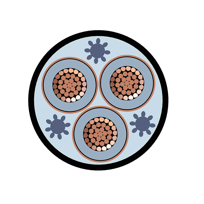
Application
Medium-voltage unarmoured cables (3.6/6kV ~ 18/30kV) are widely used in the following scenarios:
Suitable for AC 50 Hz power supply lines, such as urban underground power grids, outgoing lines of power stations and internal power networks of industrial and mining enterprises.
Industrial Facilities: Cable trays inside factory workshops and interconnection cables for power distribution rooms.
Large Public Buildings: incoming lines laid in cable trays / cable trenches in commercial complexes, data centers and hospital basements.
Transportation Hubs: Medium voltage power distribution circuits in utility tunnels and cable tunnels, wiring inside building cable shafts and transformer rooms.
Characteristics
Voltage Rating Uo/U (Um)
6/10(12)kV
Electrical Characteristics:
AC High voltage test: 3.5U0 for 5min
Partial Discharge at 1.73 U0: 10PC or better
Temperature Rating:
Maximum operating temperature of conductor: +90℃
Ambient temperature for service: -15℃ ~ +55℃
Conductor emergency operating temperature: 105℃
Conductor short-circuit operating temperature (5s): 250℃
Cable laying temperature:
Not lower than 0℃ (Preheat the cable if the ambient temperature is below 0℃).
Minimum Bending Radius During Laying
Single-core cable: 20D
Three-core cable: 15D
D refers to the actual outer diameter of the cable.
Laying Methods:
Conduit laying, trench laying, tunnel laying, shaft laying, cable tray laying, etc.
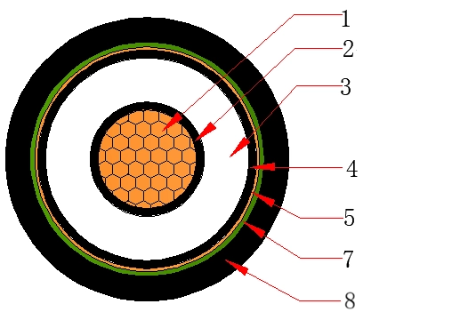
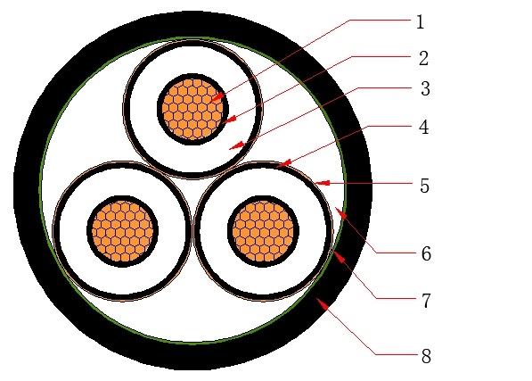
Products Construction
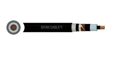
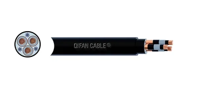
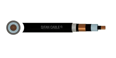
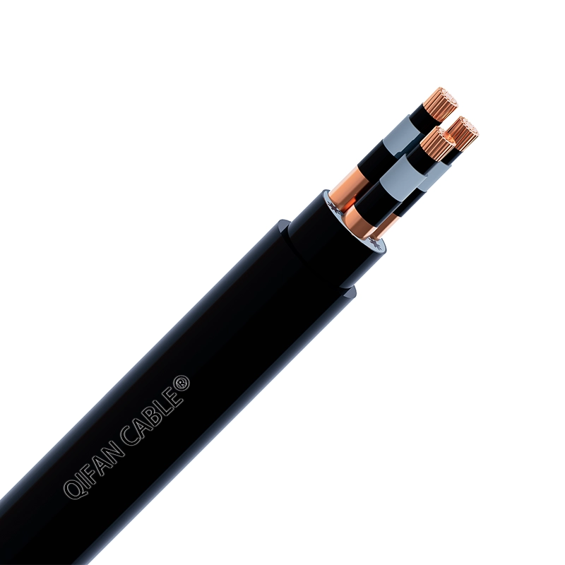
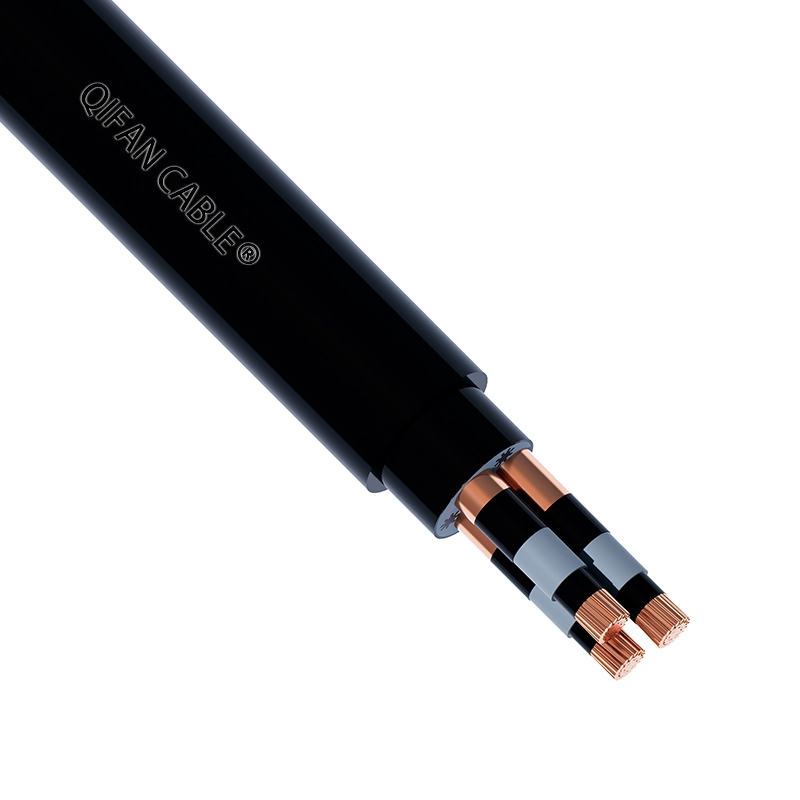
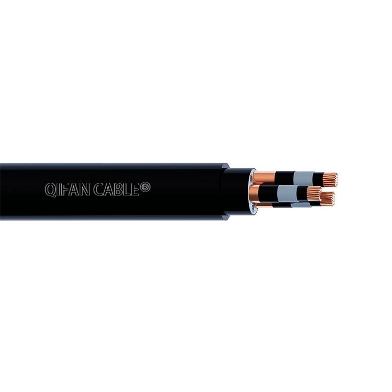
1.Conductor
Circular compacted copper conductor
2.Conductor Screen
Semi-conductive compound (for cross-section below 500mm²)
Semi-conductive tape+semi-conductive compound (for cross-section of 500mm² and above)
3.Insulation
Cross-linked polyethylene (XLPE)
4.Insulation Screen
Strippable semi-conductive compound
5.Metallic Screen
Copper tape
Copper wires
6.Filler
Non-hygroscopic filler ropes
7.Wrapping Tape
Non-hygroscopic binding tape
8.Outer Sheath
90℃ PVC (Non-fire-retardant type)
90℃ Fire-retardant PVC (Fire-retardant type)
Core Identification
Single-core: None
Three-core: Colour tape
Sheath Colour
Black or Red
Cable Drawing :
Applicable Standards
Optional
Technical Parameters
Dimensions
| Model Code | Cross-section | Conductor Diameter | Nominal Insulation Thickness | Approx. Outer Diameter of Cable | Approx. Cable Weight |
| mm² | mm | mm | mm | kg/km | |
| YJV-6/10kV | 1*25 | 5.59 | 3.4 | 18.87 | 563.4 |
| YJV-6/10kV | 1*35 | 6.62 | 3.4 | 19.90 | 674.3 |
| YJV-6/10kV | 1*50 | 7.65 | 3.4 | 20.93 | 807.4 |
| YJV-6/10kV | 1*70 | 9.21 | 3.4 | 22.66 | 1039.4 |
| YJV-6/10kV | 1*95 | 10.78 | 3.4 | 24.23 | 1309.4 |
| YJV-6/10kV | 1*120 | 12.12 | 3.4 | 25.74 | 1569.5 |
| YJV-6/10kV | 1*150 | 13.69 | 3.4 | 27.31 | 1852.5 |
| YJV-6/10kV | 1*185 | 15.21 | 3.4 | 29.00 | 2223.7 |
| YJV-6/10kV | 1*240 | 17.40 | 3.4 | 31.36 | 2796.5 |
| YJV-6/10kV | 1*300 | 19.55 | 3.4 | 33.51 | 3381.8 |
| YJV-6/10kV | 1*400 | 22.05 | 3.4 | 36.35 | 4205.0 |
| YJV-6/10kV | 1*500 | 25.00 | 3.4 | 40.10 | 5292.3 |
| YJV-6/10kV | 1*630 | 28.40 | 3.4 | 43.84 | 6687.6 |
| YJV-6/10kV | 1*800 | 33.70 | 3.4 | 49.31 | 8545.4 |
| YJV-6/10kV | 3*25 | 5.59 | 3.4 | 37.80 | 1781.7 |
| YJV-6/10kV | 3*35 | 6.62 | 3.4 | 40.19 | 2206.2 |
| YJV-6/10kV | 3*50 | 7.65 | 3.4 | 42.59 | 2648.9 |
| YJV-6/10kV | 3*70 | 9.21 | 3.4 | 46.13 | 3367.3 |
| YJV-6/10kV | 3*95 | 10.78 | 3.4 | 49.86 | 4256.8 |
| YJV-6/10kV | 3*120 | 12.12 | 3.4 | 52.92 | 5076.1 |
| YJV-6/10kV | 3*150 | 13.69 | 3.4 | 56.48 | 5985.5 |
| YJV-6/10kV | 3*185 | 15.21 | 3.4 | 59.94 | 7187.1 |
| YJV-6/10kV | 3*240 | 17.40 | 3.4 | 64.84 | 8939.1 |
| YJV-6/10kV | 3*300 | 19.55 | 3.4 | 69.82 | 10818.4 |
| YJV-6/10kV | 3*400 | 22.05 | 3.4 | 75.56 | 13375.4 |
| YJV-6/10kV | 3*500 | 25.00 | 3.4 | 84.00 | 16975.0 |
| YJV-6/10kV | 3*630 | 28.40 | 3.4 | 91.86 | 21439.2 |
Electrical Characteristics
Single Core
| Cross-section | Max. Coductor DC Resistance at 20℃ | Max. Coductor AC Resistance at 90℃ | Capacitance | Fault Current Capacity | Positive and Negative Sequence Impedance | Zero-sequence impedance (single-end grounded | |||
| Conductor | Metallic Screen | Trefoil | Flat | Trefoil | Flat | ||||
| mm² | Ω/km | Ω/km | μF/km | kA/1s | kA/1s | Ω/km | Ω/km | Ω/km | Ω/km |
| 1×25 | 0.727 | 0.927 | 0.2173 | 3.7 | 0.73 | 0.927+j0.135 | 0.927+j0.193 | 1.075+j0.871 | 1.075+j0.784 |
| 1×35 | 0.524 | 0.668 | 0.2300 | 5.1 | 0.73 | 0.668+j0.127 | 0.668+j0.185 | 0.816+j0.857 | 0.816+j0.770 |
| 1×50 | 0.387 | 0.494 | 0.2510 | 7.3 | 0.73 | 0.494+j0.119 | 0.494+j0.177 | 0.642+j0.838 | 0.642+j0.751 |
| 1×70 | 0.268 | 0.342 | 0.2844 | 10.2 | 0.73 | 0.342+j0.113 | 0.342+j0.171 | 0.490+j0.819 | 0.490+j0.732 |
| 1×95 | 0.193 | 0.246 | 0.3197 | 13.8 | 0.73 | 0.247+j0.108 | 0.246+j0.166 | 0.395+j0.800 | 0.394+j0.713 |
| 1×120 | 0.153 | 0.196 | 0.3467 | 17.4 | 0.73 | 0.196+j0.104 | 0.196+j0.162 | 0.344+j0.786 | 0.343+j0.699 |
| 1×150 | 0.124 | 0.159 | 0.3756 | 21.8 | 0.73 | 0.159+j0.101 | 0.159+j0.159 | 0.307+j0.772 | 0.307+j0.685 |
| 1×185 | 0.0991 | 0.1271 | 0.4087 | 26.8 | 0.73 | 0.127+j0.097 | 0.127+j0.155 | 0.275+j0.758 | 0.275+j0.671 |
| 1×240 | 0.0754 | 0.0972 | 0.4540 | 34.7 | 0.73 | 0.098+j0.094 | 0.097+j0.152 | 0.246+j0.740 | 0.245+j0.653 |
| 1×300 | 0.0601 | 0.0779 | 0.4972 | 43.4 | 0.73 | 0.079+j0.091 | 0.078+j0.149 | 0.227+j0.725 | 0.226+j0.638 |
| 1×400 | 0.0470 | 0.0616 | 0.5485 | 57.8 | 0.73 | 0.063+j0.087 | 0.062+j0.145 | 0.210+j0.706 | 0.209+j0.619 |
| 1×500 | 0.0366 | 0.0488 | 0.6122 | 72.2 | 0.73 | 0.050+j0.085 | 0.049+j0.143 | 0.198+j0.689 | 0.197+j0.602 |
| 1×630 | 0.0283 | 0.0388 | 0.6819 | 90.8 | 0.73 | 0.041+j0.083 | 0.039+j0.141 | 0.188+j0.671 | 0.187+j0.584 |
| 1×800 | 0.0221 | 0.0316 | 0.8007 | 115.3 | 0.73 | 0.034+j0.084 | 0.032+j0.142 | 0.182+j0.647 | 0.180+j0.560 |
Three Cores
| Cross-section | Max. Coductor DC Resistance at 20℃ | Max. Coductor AC Resistance at 90℃ | Capacitance | Inductance | Impedance | Fault Current Capacity | Positive and Negative Sequence Impedance | Zero-sequence impedance (single-end grounded) | |
| Conductor | Metallic Screen | ||||||||
| mm² | Ω/km | Ω/km | μF/km | mH/km | Ω/km | kA/1s | kA/1s | Ω/km | Ω/km |
| 3×25 | 0.727 | 0.927 | 0.2173 | 0.4025 | 0.9357 | 3.7 | 1.92 | 0.927+j0.122 | 1.075+j0.898 |
| 3×35 | 0.524 | 0.668 | 0.2300 | 0.3907 | 0.6795 | 5.1 | 1.92 | 0.668+j0.114 | 0.817+j0.883 |
| 3×50 | 0.387 | 0.494 | 0.2510 | 0.3740 | 0.5075 | 7.3 | 1.92 | 0.494+j0.106 | 0.642+j0.864 |
| 3×70 | 0.268 | 0.342 | 0.2844 | 0.3444 | 0.3588 | 10.2 | 1.92 | 0.342+j0.101 | 0.490+j0.843 |
| 3×95 | 0.193 | 0.247 | 0.3197 | 0.3272 | 0.2672 | 13.8 | 1.92 | 0.247+j0.096 | 0.395+j0.823 |
| 3×120 | 0.153 | 0.196 | 0.3467 | 0.3165 | 0.2197 | 17.4 | 1.92 | 0.196+j0.093 | 0.344+j0.808 |
| 3×150 | 0.124 | 0.159 | 0.3756 | 0.3044 | 0.1856 | 21.8 | 1.92 | 0.159+j0.090 | 0.307+j0.793 |
| 3×185 | 0.0991 | 0.1276 | 0.4087 | 0.2951 | 0.1578 | 26.8 | 1.92 | 0.128+j0.087 | 0.276+j0.779 |
| 3×240 | 0.0754 | 0.0978 | 0.4540 | 0.2846 | 0.1326 | 34.7 | 1.92 | 0.098+j0.084 | 0.246+j0.760 |
| 3×300 | 0.0601 | 0.0788 | 0.4972 | 0.2750 | 0.1171 | 43.4 | 1.92 | 0.079+j0.082 | 0.227+j0.744 |
| 3×400 | 0.0470 | 0.0628 | 0.5485 | 0.2670 | 0.1049 | 57.8 | 1.92 | 0.063+j0.078 | 0.211+j0.725 |
| 3×500 | 0.0366 | 0.0504 | 0.6122 | 0.2508 | 0.0937 | 72.2 | 1.92 | 0.051+j0.077 | 0.199+j0.706 |
| 3×630 | 0.0283 | 0.0409 | 0.6819 | 0.2406 | 0.0861 | 90.8 | 1.92 | 0.041+j0.075 | 0.189+j0.688 |
Correction factors for ampacity
| Conductor operating temperature (℃) | Temperature in air (℃) | |||||||
| 20 | 25 | 30 | 35 | 40 | 45 | 50 | 55 | |
| 90 | 1.21 | 1.16 | 1.11 | 1.06 | 1.00 | 0.94 | 0.88 | 0.81 |
| Conductor operating temperature (℃) | Temperature in soil (℃) | |||||
| 10 | 15 | 20 | 25 | 30 | 35 | |
| 90 | 1.11 | 1.07 | 1.04 | 1.00 | 0.96 | 0.92 |
| Conductor operating temperature (℃) | Soil thermal resistivity (K·m/W) -direct burial | ||||||
| 0.7 | 1 | 1.2 | 1.5 | 2 | 2.5 | 3 | |
| 90 | 1.13 | 1.00 | 0.93 | 0.86 | 0.76 | 0.69 | 0.64 |
| Conductor operating temperature (℃) | Soil thermal resistivity (K·m/W) -conduit burial | ||||||
| 0.7 | 1 | 1.2 | 1.5 | 2 | 2.5 | 3 | |
| 90 | 1.08 | 1.00 | 0.96 | 0.90 | 0.82 | 0.77 | 0.72 |
| Conductor operating temperature (℃)) | Burial depth in soil (m) -direct burial | |||||
| 0.5 | 0.7 | 1.0 | 1.5 | 2.0 | 2.5 | |
| 90 | 1.07 | 1.03 | 1.00 | 0.96 | 0.94 | 0.92 |
| Conductor operating temperature (℃) | Burial depth in soil (m) – in conduit | |||||
| 0.5 | 0.7 | 1.0 | 1.5 | 2.0 | 2.5 | |
| 90 | 1.04 | 1.02 | 1.00 | 0.98 | 0.96 | 0.95 |
For single-core cables arranged in a trefoil formation, the cables are in contact with each other; when installed in ducts, the ducts are in contact with each other.
For single-core cables arranged in parallel with spacing, the axial distance between cables is 2 times the cable outer diameter.
For calculations under base conditions, the burial depth in soil is taken as 1.0 m, and the soil thermal resistivity is taken as 1.0 K·m/W.
Depending on the soil type, the corresponding soil conditions and meteorological conditions for different thermal resistivities are approximately as follows:
- 0.7: Soil condition: Very wet; Meteorological condition: Continuous rainfall
- 1.0: Soil condition: Wet; Meteorological condition: Normal rainfall
- 2.0: Soil condition: Dry; Meteorological condition: Infrequent rainfall
- 3.0: Soil condition: Very dry; Meteorological condition: Rare or no rainfall
The ducts are plastic pipes. (Assume the duct inner diameter is 1.5 times the cable outer diameter, and the duct wall thickness is 6% of the duct inner diameter.)
The metallic screen is not directly grounded at both ends.
FAQ
Unarmoured cables have no steel wire/steel tape armour. They rely only on insulation and outer sheath. They are suitable for protected locations with low risk of mechanical damage (cuts, crushing, impact, rodent attack).
The key difference is mechanical protection requirement.
MV unarmoured cable is selected where the cable route has reliable external protection (duct, tunnel, indoor cable tray).
MV armoured cable is chosen for unprotected routes such as direct burial, open outdoor overhead laying or areas vulnerable to mechanical damage.
Generally not recommended. Even with anti-UV outer sheath, unarmoured cable lacks anti-impact and anti-abrasion capacity. Exposed outdoor laying faces risks of collision, stone impact and animal damage. If outdoor use is required, the cable must be arranged within trunking or cable enclosure.
Direct burial underground without conduit
Exposed outdoor open-air runs
Construction sites, areas with moving heavy machinery
Locations with high rodent / termite risk
Routes subject to frequent impact, abrasion or crushing